Download
1 / 28
280 likes | 452 Views
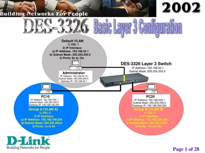
Basic Layer 3 Configuration. DES-3326. Default VLAN. 1) VID: 1. 2) IP Interface:. a) IP Address: 192.168.22.1. b) Subnet Mask: 255.255.255.0. 3) Ports: 9x to 16x. DES-3326 Layer 3 Switch. IP Address: 192.168.22.1. Subnet Mask: 255.255.255.0. Administrator. IP Address: 192.168.22.10.

E N D
Basic Layer 3 Configuration DES-3326 Default VLAN 1) VID: 1 2) IP Interface: a) IP Address: 192.168.22.1 b) Subnet Mask: 255.255.255.0 3) Ports: 9x to 16x DES-3326 Layer 3 Switch IP Address: 192.168.22.1 Subnet Mask: 255.255.255.0 Administrator IP Address: 192.168.22.10 Subnet Mask: 255.255.255.0 Gateway IP: 192.168.22.1 PC10 PC20 IP Address: 192.168.200.1 IP Address: 192.168.100.1 Subnet Mask: 255.255.255.0 Subnet Mask: 255.255.255.0 Gateway IP: 192.168.100.254 Gateway IP: 192.168.200.254 Group A (VLAN A) Group B (VLAN B) 1) VID: 2 1) VID: 3 2) IP Interface: 2) IP Interface: a) IP Address: 192.168.100.254 a) IP Address: 192.168.200.254 b) Subnet Mask: 255.255.255.0 b) Subnet Mask: 255.255.255.0 3) Ports: 1x to 8x 3) Ports: 17x to 24x
Basic Layer 3 Configuration 2.1) Firstly, ensure that your Console (RS-232) cable is connected from your computer to the DES-3326 Switch. 2.2) Execute the “Hyper Terminal” program. (as shown above) 2.3) Key in the “User name” & “Password” as prompted.
Basic Layer 3 Configuration 3.1) Select the <Remote Management Setup> option.
Basic Layer 3 Configuration 4.1) Key in this Switch’s IP Address in the <IP Address:>, and also key in this Switch’s Subnet Mask in the <Subnet Mask:>.Example: 192.168.22.1 {IP} 255.255.255.0 {Subnet Mask}. 4.2) Next, select the <APPLY> option.
Basic Layer 3 Configuration 5.1) Go back to the <Main Menu>. 5.2) Select the <Save Changes> option.
Basic Layer 3 Configuration 6.1) Wait till you see the sentence “Press any key to continue” (in the above screen). 6.2) Next, press any key.
Basic Layer 3 Configuration 7.1) Select the <Switch Settings> option.
Basic Layer 3 Configuration 8.1) Select the <Switch Operation Mode> option.
Basic Layer 3 Configuration 9.1) Press <Space Bar>, to select “IP Routing, Support IEEE 802.1Q VLANs”. 9.2) Next, select <Apply> option.
Basic Layer 3 Configuration 10.1) Key in “y”, when you are prompted (shown above). 10.2) Next, wait till the Switch finish its rebooting.
Basic Layer 3 Configuration 11.1) Ensure that you see “Layer 3 Switch” at the top right corner. If not, please repeat this configuration from Step 7.1 11.2) Key in the “User name” & “Password” as prompted.
Basic Layer 3 Configuration 12.1) Select the <VLANs> option.
Basic Layer 3 Configuration 13.1) Select the <Edit 802.1Q VLANs> option.
Basic Layer 3 Configuration 14.1) In the <VID>, key in “2”.14.2) In the <VLAN Name>, key in “VLANA”.14.3) Set port 1 to 8’s <Membership> and <Tagging> to “E” and “U”.* Note: Use the <E> and <U> keys on your Keyboard.14.4) Next, select the <APPLY> option.14.5) Ensure that “VLANA” entry appears after you applied these settings. If not, please repeat this configuration from Step 14.1
Basic Layer 3 Configuration 15.1) In the <VID>, key in “3”.15.2) In the <VLAN Name>, key in “VLANB”.15.3) Set port 17 to 24’s <Membership> and <Tagging> to “E” and “U”.* Note: Use the <E> and <U> keys on your Keyboard.15.4) Next, select the <APPLY> option.15.5) Ensure that “VLANB” entry appears after you applied these settings. If not, please repeat this configuration from Step 15.1
Basic Layer 3 Configuration 16.1) Next, select the <Configure 802.1Q Port Settings> option.
Basic Layer 3 Configuration 17.1) In the <Configure Port from [ ] to [ ]>, key in “1” and “8”. 17.2) In the <PVID> , key in “2”. 17.3) Next, select the <APPLY> option. 17.4) After the applying the above settings, ensure that from Port 1 to 8, you see PVID=2. If not, please repeat this configuration from Step 17.1.
Basic Layer 3 Configuration 18.1) In the <Configure Port from [ ] to [ ]>, key in “17” and “24”. 18.2) In the <PVID> , key in “3”. 18.3) Next, select the <APPLY> option. 18.4) After the applying the above settings, ensure that from Port 17 to 24, you see PVID=3. If not, please repeat this configuration from Step 18.1.
Basic Layer 3 Configuration 19.1) Select the <Layer 3 IP Networking> option.
Basic Layer 3 Configuration 20.1) Select the <Setup IP Interface> option.
Basic Layer 3 Configuration 21.1) In the <Interface Name>, key in “GroupA”.21.2) In the <IP Address>, key in “192.168.100.254”.21.3) In the <Subnet Mask>, key in “255.255.255.0”.21.4) In the <VID>, key in “2”.21.5) Next, select the <APPLY> option.21.6) After the applying the above settings, ensure that you see the above settings are shown. If not, please repeat this configuration from Step 21.1.
Basic Layer 3 Configuration 22.1) In the <Interface Name>, key in “GroupB”.22.2) In the <IP Address>, key in “192.168.200.254”.22.3) In the <Subnet Mask>, key in “255.255.255.0”.22.4) In the <VID>, key in “3”.22.5) Select the <APPLY> option.22.6) Follow by, pressing the <CTRL> and <N> keys (on your keyboard), to view the next page.22.7) After the applying the above settings, ensure that you see the above settings are shown. If not, please repeat this configuration from Step 22.1.
Basic Layer 3 Configuration 1 3 2 5 4 23.1) At “PC10” (GroupA computer), execute the <MS-DOS Prompt>.23.2) Key in “ping 192.168.100.1” (its own IP address), and press the <Enter> key.23.3) Key in “ping 192.168.100.254” (its own VLAN Interface IP address), and press the <Enter> key.23.4) Key in “ping 192.168.22.1” (DES-3326’s IP address), and press the <Enter> key.23.5) Key in “ping 192.168.200.254” (VLAN B Interface IP address) , and press the <Enter> key.23.6) Key in “ping 192.168.200.1” (VLAN B computer’s IP address) , and press the <Enter> key.23.7) Ensure that all the above mentioned “Ping” have “reply”.
Basic Layer 3 Configuration 1 3 2 4 5 24.1) At “PC20” (GroupB computer), execute the <MS-DOS Prompt>.24.2) Key in “ping 192.168.200.1” (its own IP address), and press the <Enter> key.24.3) Key in “ping 192.168.200.254” (its own VLAN Interface IP address), and press the <Enter> key.24.4) Key in “ping 192.168.22.1” (DES-3326’s IP address), and press the <Enter> key.24.5) Key in “ping 192.168.100.254” (VLAN A Interface IP address) , and press the <Enter> key.24.6) Key in “ping 192.168.100.1” (VLAN A computer’s IP address) , and press the <Enter> key.24.7) Ensure that all the above mentioned “Ping” have “reply”.
Basic Layer 3 Configuration 23.1) Next, select the <Network Monitoring> option.
Basic Layer 3 Configuration 24.1) Select the <Routing Table> option.
Basic Layer 3 Configuration 25.1) Ensure that you see the above entries (shown above). If not, please repeat this configuration from Step 19.1 * Note: The above entries will only show when there are network traffics between the IP segments or VLANs (Example: GroupA’s computer ping GroupB’s Computer).
Basic Layer 3 Configuration 26.1) Select the <Logout> option. 26.2) Lastly, you may close the “Hyper Terminal” program. === The End ===