Download
1 / 46
460 likes | 588 Views
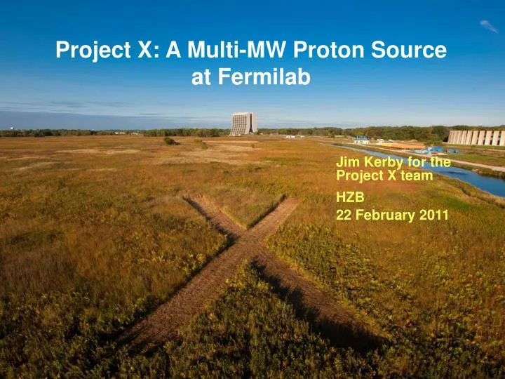
Project X: A Multi-MW Proton Source at Fermilab. Jim Kerby for the Project X team HZB 22 February 2011. Outline. Strategic Context/Evolution of the Fermilab Complex Project X Goals and Reference Design Project X R&D Program Strategy/Timeline Project X website: http://projectx.fnal.gov.

E N D
Project X: A Multi-MW Proton Sourceat Fermilab Jim Kerby for the Project X team HZB 22 February 2011
Outline • Strategic Context/Evolution of the Fermilab Complex • Project X Goals and Reference Design • Project X R&D Program • Strategy/Timeline Project X website: http://projectx.fnal.gov HZB Feb 2011 – J. Kerby
Strategic Context: Fermilab and the World Program • The Tevatron was the highest energy particle collider in the world for 25 years • Energy frontier now ceded to LHC • Fermilab operates the highest power long baseline neutrino beam in the world. • J-PARC is initiating a competitive program To Soudan HZB Feb 2011 – J. Kerby
Evolution of the Fermilab Accelerator Complex • A multi-MW Proton Source, Project X, is the linchpin of Fermilab’s strategy for future development of the accelerator complex. • Project X provides long term flexibility for achieving leadership on the intensity and energy frontiers • Intensity Frontier: NuMI NOnA LBNE/mu2e Project X Rare Processes NuFact • Continuously evolving world leading program in neutrino and rare processes physics; opportunities for applications outside EPP • Energy Frontier: Tevatron ILC or Muon Collider • Technology alignment • Fermilab as host site for ILC or MC HZB Feb 2011 – J. Kerby
Mission • A neutrino beam for long baseline neutrino oscillation experiments • 2 MW proton source at 60-120 GeV • High intensity, low energy protons for kaon and muon based precision experiments • Operations simultaneous with the neutrino program • A path toward a muon source for possible future Neutrino Factory and/or a Muon Collider • Requires ~4 MW at ~5-15 GeV . • Possible missions beyond P5 • Standard Model Tests with nuclei and energy applications
Accelerator Requirements: Rare Processes HZB Feb 2011 – J. Kerby
Reference Design HZB Feb 2011 – J. Kerby
Functional Requirements HZB Feb 2011 – J. Kerby
Functional Requirements HZB Feb 2011 – J. Kerby
Siting HZB Feb 2011 – J. Kerby
R&D Program • The primary elements of the R&D program include: • Development of a wide-band chopper • Capable of removing bunches in arbitrary patterns at a 162.5 MHz bunch rate • Development of an H- injection system • Require between 4.4 – 26 msec injection period, depending on pulsed linac operating scenario • Superconducting rf development • Includes six different cavity types at three different frequencies • Includes development of partners • Goal is to complete R&D phase by 2015 HZB Feb 2011 – J. Kerby
SRF LinacTechnology Map Pulsed CW 650 MHz 0.16-3 GeV b=0.11 b=0.22 b=0.4 b=0.61 b=0.9 b=1.0 325 MHz 2.5-160 MeV 1.3 GHz 3-8 GeV HZB Feb 2011 – J. Kerby
3 GeV CW LinacEnergy Gain per Cavity b=0.9 b=0.61 • Based on 5-cell 650 MHz cavity • Crossover point ~450 - 500 MeV HZB Feb 2011 – J. Kerby
3 GeV CW LinacRF Power per Cavity • Single cavity per power source • Solid State, IOT HZB Feb 2011 – J. Kerby
3 GeV CW LinacCryogenic Losses per Cavity ~42 kW cryogenic power at 4.5 K equivalent HZB Feb 2011 – J. Kerby
SRF DevelopmentCavity/ CM Status • 1300 MHz (ILC - type, Pulsed Linac) • 88 nine-cell cavities ordered • ~ 44 received (16 from a U.S. industry, AES) • ~ 30 processed and tested, 8 dressed • 1 CM built (DESY kit) + second under construction (U.S. procured) • CM1 is now cold and under initial RF testing • 650 MHz: • MOU signed with Jlab for 2 single cell b =0.61 cavities • Initial b =0.9 cavity shapes stamped at RRCAT • Order for six b = 0.9 single cell cavities in US industry • 325 MHz: • 2 SSR1 b =0.22 cavities (Roark, Zanon) both VTS tested • 2 SSR1 near completion at IUAC • 10 SSR1 ordered from Industry (Roark) • Design work started on 325 and 650 MHz CM HZB Feb 2011 – J. Kerby
SRF Development325 MHz • SSR1 (b=0.22) cavity under development • Two prototypes assembled and tested • Both meet Project X specification at 2 K • Preliminary designs for SSR0 and SSR2 HZB Feb 2011 – J. Kerby
SRF Development650 MHz • Initial design concepts completed • Single cell models being made HZB Feb 2011 – J. Kerby
SRF Development1300 MHz • Cavity development is being undertaken in the U.S. as part of the ILC program • ILC goal: 31.5 MV/m (average CM gradient); Q0=8x10⁹ • Project X goals: 25 MV/m; Q0=1x10¹⁰ • Development undertaken by a U.S. consortium of labs/universities/industry • Fermilab, JLab, Argonne, Cornell • Cavites from U.S. and European vendors • Substantial investment in infrastructure at Fermilab • Vertical and horizontal test stands • Cavity and cryomodule assembly areas • ILCTA_NML • Goal is to have capability of 1 CM/month by 2015 HZB Feb 2011 – J. Kerby
SRF Development1300 MHz PrX ILC HZB Feb 2011 – J. Kerby
NML Test Facility • The New Muon Laboratory (NML) Test Facility ultimately comprises: • Complete Test of ILC RF unit (with beam) • Three 1.3GHz CM’s driven from a single rf source • 9mA x 1 msec pulse • Beam Test Lines for • Crab Cavity Tests • Upgrades for beam tests up to • 6 ILC type Cryomodules from two rf sources • AARD experiments and beam studies • Shared Cryogenic Infrastructure for • 1.3GHz Cryomodule Test Stands • 650 MHz Cryomodule Test Stands HZB Feb 2011 – J. Kerby
NML Facility Layout Future 3.9/Crab Cavity Test Beamlines Capture Cavity 1 (CC1) Cryomodules CC2 RF Gun 5MW RF System for Gun CC1 & CC2 RF Systems 5MW RF System for Cryomodules Future 10MW RF System HZB Feb 2011 – J. Kerby 22
ILCTA_NML Facility HZB Feb 2011 – J. Kerby
CM1 Just Prior to Cooldown HZB Feb 2011 – J. Kerby
Future NML Complex New Cryoplant & CM Test Facility (300 W Cryogenic Plant, Cryomodule Test Stands, 10 MW RF Test Area) New Underground Tunnel Expansion (Space for 6 Cryomodules (2 RF Units), AARD Test Beam Lines) HZB Feb 2011 – J. Kerby
Cryoplant Building Construction HZB Feb 2011 – J. Kerby
MDB Test Facility • The Meson Detector Building (MDB) Test Facility ultimately comprises: • A shielded beam line enclosure with first proton, then H-, pulsed 1% duty factor, 3 millisecond beam up to 10MeV • For Project X 325 MHz superconducting spoke cavity beam tests • For Project X chopper tests • For Project X H- beam instrumentation development • Shielded enclosures and RF power systems for testing individual, jacketed 1.3 GHz, 650 MHz, and 325 MHz superconducting RF cavities (no beam) • For ILC • For Project X HZB Feb 2011 – J. Kerby
MDB Test Facility Layout 325 MHz Spoke Cavity Test Facility 1.3 GHz HTS HTS-2 650 CW RF 1300 CW RF 325 CAGE Scale: Square blocks are 3ft x 3ft Source of cryogenics Ion Source and RFQ MDB Linac enclosure for 10 MEV HZB Feb 2011 – J. Kerby
MDB Test Facility325 MHz RFQ HZB Feb 2011 – J. Kerby
MDB Long Term PlanChopper and 4-Cavity CM 18° spectrometer ~2.7 m length Actual absorber/shielding 10 m MEBT/CHOPPER 13.4 m Existing ion source and RFQ 0 m 10.5 m 16.9 m 14.2 m 10.5 foot ceiling 0.5 m end 0.5 m end 2.4 m cryostat With cryomodule need additional 3+ meters cave length pending spectrometer line optics design HZB Feb 2011 – J. Kerby
Collaboration • A multi-institutional collaboration has been established to execute the Project X RD&D Program. • Organized as a “national project with international participation” • Fermilab as lead laboratory • International participation via in-kind contributions, established through bi-lateral MOUs. • IIFC Agreement in place and operating • Collaboration MOUs for the RD&D phase outlines basic goals, and the means of organizing and executing the work. Signatories: ANL ORNL/SNS BARC/Mumbai BNL MSU IUAC/Delhi Cornell TJNAF RRCAT/Indore Fermilab SLAC VECC/Kolkata LBNL ILC/ART • It would be natural for collaborators to continue their areas of responsibility into the construction phase. HZB Feb 2011 – J. Kerby
Summary • Project X is central to Fermilab’s strategy for development of the accelerator complex over the coming decade • World leading programs in neutrinos and rare processes • Aligned with ILC and Muon Accelerators technology development; • Potential applications beyond elementary particle physics • The design concept has evolved over the last year, providing significantly enhanced physics capabilities • 2 MW to the neutrino program over 60-120 GeV • 3 MW to the rare processes program • Flexible provision for variable beam formats to multiple users • CW linac is unique for this application, and offers capabilities that would be hard/impossible to duplicate in a synchrotron • We are executing the R&D Plan to establish design, demonstrate technologies and prepare for construction starting in 2015 • Includes vendor development • Establish collaboration for construction HZB Feb 2011 – J. Kerby
Fermilab Long Range Plan Fermilab is the sole remaining U.S. laboratory providing facilities in support of accelerator-based Elementary Particle Physics. Fermilab is fully aligned with the strategy for U.S. EPP developed by HEPAP/P5. • The Fermilab strategy is to mount a world-leading program at the intensity frontier, while using this program as a bridge to an energy frontier facility beyond LHC in the longer term. HZB Feb 2011 – J. Kerby
Reference Design Scope • 3 GeV CW superconducting H- linac, capable of delivering 1 mA average beam current. • Flexible provision for variable beam structures to multiple users • Starts at ion source; ends at 3-way split (with stubs) • Supports rare processes programs • Provision for 1 GeV extraction for nuclear energy program • 3-8 GeV pulsed linac capable of delivering 300 kW at 8 GeV • Supports the neutrino program • Establishes a path toward a muon based facility • Upgrades to the Recycler and Main Injector to provide ≥ 2 MW to the neutrino production target at 60-120 GeV. • Ends at MI extraction kicker • Supports the long baseline neutrino program • Interconnecting beamlines HZB Feb 2011 – J. Kerby
Capabilities • > 2 MW delivered to a neutrino target at any energy between 60 – 120 GeV • Simultaneous delivery of ~3 MW of high duty factor beam power to the 3 GeV program • Variable beam formats to multiple users • CW beam at time scales >1 msec • 10% duty factor on time scales < 1 msec • Potential for development of additional programs at: • 1 GeV for nuclear energy experimentation • 8 GeV for neutrino or muon experimentation • The utilization of a CW linac creates a facility that is unique in the world, with performance that is unlikely to be duplicated in any synchrotron-based facility. HZB Feb 2011 – J. Kerby
R&D ProgramWideband Chopper • Approach • Four wideband kickers place at 180o in the 2.5 MeV MEBT • Helical or meander-stripline travelling wave deflectors • Wideband amplifier • Requirements • 1 nsec rise/fall time • 1 nsec flat top pulse duration • 150-200 Ω load impedance • >500 V pulse amplitude • >60 MHz average repetition rate • Performance (simulation) • 0.16% beam loss with kicker off • 100% beam removal with kicker on HZB Feb 2011 – J. Kerby
R&D Program H- Injection • RDR Configuration • Inject and accumulate into the Recycler with single turn transfer to MI • Injection charge 26 mA-ms (1 mA – 4.3 ms – 6 injections and 10 Hz) • Optional Configuration of interest • Inject 1 mA directly into the Main Injector in a single pulse over 26 ms, bypassing the Recycler • Reduced complexity • Reduced linac energy, from 8 to 6 GeV • Default technology Carbon Foil Charge Exchange (stationary foil) • Low beam current/long injections time creates many “parasitic” interactions, and dominate the foil issues: • Foil heating, beam loss, emittance growth. (c.f. 1 mA 2300 turns) • The number of parasitic hits is determined by injection insertion design, number of injection turns (linac intensity and injection time), linac and ring emittance, painting algorithm, foil size and orientation. • Issues appear manageable up to about 4.3 msec (400 turns). HZB Feb 2011 – J. Kerby
Operating Scenario3 GeV Program 1 msec period at 3 GeV Muon pulses (12e7) 162.5 MHz, 80 nsec 750 kW Kaon pulses (12e7) 27 MHz 1500 kW Nuclear pulses (12e7) 13.5 MHz 750 kW Ion source and RFQ operate at 6.2 mA 83% of bunches are chopped @ 2.5 MeV maintain 1 mA over 1 msec Separation scheme Transverse rf splitter HZB Feb 2011 – J. Kerby
Pulsed Linac • The Reference Design utilizes a superconducting pulsed linac for acceleration from 3 to 8 GeV • ILC style cavities and cryomodules • 1.3 GHz, b=1.0 • 28 cryomodules (@ 25 MV/m) • ILC style rf system • 5 MW klystron • Up to four cryomodules per rf source • Must deliver 26 mA-msec to the Recycler every 0.75 sec. Options: • 1 mA x 4.4 msec pulses at 10 Hz • Six pulses required to load Recycler/Main Injector • 1 mA x 26 msec pulses at 10 Hz • One pulse required to load Main Injector HZB Feb 2011 – J. Kerby
SRF Development1300 MHz Cavity Vertical Tests ILC PX (pulsed) • European and American vendors • Cavity processing at JLab, Cornell, and Fermilab/ANL HZB Feb 2011 – J. Kerby
3 GeV CW LinacChoice of Cavity Parameters • Identify maximum achievable surface (magnetic field) on basis of observed Q-slope “knee” • Select cavity shape to maximize gradient (subject to physical constraints) • Establish Q goal based on realistic extrapolation from current performance • Goal: <25 W/cavity • Optimize within (G, Q, T) space (Initial) Performance Goals Freq (MHz) Bpk(mT) G (MV/m) Q @T (K) 325 60 15 1.4E10 2 650 72 16 1.7E10 2 HZB Feb 2011 – J. Kerby
Fermilab SRF infrastructure 1st Dressed Cavity Cavity tuning machine VTS HTS VTS String Assembly MP9 Clean Room Final Assembly 1st U.S. built ILC/PX Cryomodule
Cavity processing at ANL Ultrasonic Cleaning • Joint facility built by ANL/FNAL collaboration • EP processing of 9-cells has started • Together with Jlab, ANL/FNAL facility represents the best cavity processing facilities in the US for ILC or Project X Electropolishing High-pressure rinse HZB Feb 2011 – J. Kerby
FNAL IB4 Tumbling Facility Multi-step process for elliptical cavities using multiple sets of media Current results represent an intermediate step towards a more complete process Much less infrastructure required Complete descriptions in prep for publication, presentation at TTC, SRF 2011 HZB Feb 2011 – J. Kerby
U.S. Department of Energy Process • Process is governed by five “Critical Decisions”: • CD-0: Approve Mission Need • CD-1: Approve Alternative Selection and Cost Range • CD-2: Approve Performance Baseline • CD-3: Approve Start of Construction • CD-4: Approve Start of Operations or Project Completion • Most projects undertaken in the last decade have take between 3 to 4 years to get from CD-0 to CD-3 • CD-0 documentation is submitted and we are anticipating approval in spring 2011 • Planning for a five year construction schedule • Project X could be up and running in ~2020 HZB Feb 2011 – J. Kerby