Download
1 / 45
520 likes | 883 Views
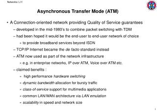
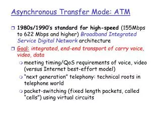
Asynchronous Transfer Mode. Developed as part of broadband ISDN used in private non-ISDN networks Also called Cell Relay More streamlined than Frame Relay Supports speeds at 155.52 Mbps and 622.08 Mbps Higher and lower speeds are possible. ATM.

E N D
Asynchronous Transfer Mode • Developed as part of broadband ISDN • used in private non-ISDN networks • Also called Cell Relay • More streamlined than Frame Relay • Supports speeds at 155.52 Mbps and 622.08 Mbps • Higher and lower speeds are possible
ATM • Data is organised into fixed-size packets called cells • This simplifies the process of switching data at each node • Protocol is streamlined with minimal overhead
ATM Protocol Structure Management plane Control Plane User Plane Higher Layer protocols Higher Layer protocols ATM Adaptation Layer ATM Layer Physical Layer Plane management Layer management
ATM layer • Logical connections are called virtual channel connections (VCC) • Full-duplex, fixed-size cell, variable rate connection between users is established on a VCC • VCC also used for user-network control signalling and network management and routing
ATM layer • VCCs are bundled into groups that have same endpoints • These are called virtual path connections (VPC) • All cells in all VCCs in a VPC are switched together
Advantages of VPC • Network transport functions can be split into those for individual VCCs and those for groups of VCCs in VPCs • Network deals with smaller number of entities • Increased network performance • When VPC is established new VCCs can be set up with no transit node processing
VCC Uses • Between end-users • VPC between users provides overall capacity • VCCs can be organised between the users up to VPC capacity • End user - network used for control signalling • Network-network used for network traffic management and routing
Characteristics of VPC/VCC • Switched and semi-permanent connections • Packet sequence is preserved • Traffic parameters can be negotiated (e.g.peak and average rate) • Quality of service is specified (cell loss ratio, delay variation)
Control Signalling for VCCs • Not needed for semi-permanent connection • Takes place on separate signalling channel • Meta-signalling channel is a permanent channel used to set up signalling channel • This can be used to set up a user-to-network signalling channel • This can also be used to set up a user-to-user signalling channel within an existing VPC which users can use to set up user-user VCC
Control Signalling for VPCs • Not needed for semi-permanent connection • Customer controlled VPC • Signalling VCC used by user to request/release VPC • Network controlled VPC • Network establishes VPC for own use. It may be • Network-network • User-to-network • User-user
ATM Cell Format 8 7 6 5 4 3 2 1 Generic flow control Virtual Path Identifier Virtual Path Identifier Virtual channel ident Virtual channel Identifier Virtual channel ident Payload type CLP Header error control Information Field (48 octets) User-network interface
ATM Cell Format 8 7 6 5 4 3 2 1 Virtual Path Identifier Virtual Path Identifier Virtual channel ident Virtual channel Identifier Virtual channel ident Payload type CLP Header error control Information Field (48 octets) Network-network interface
Header Error Control Multi-bit error detected (cell discarded) no error detected (no action) Correction Mode Detection Mode no error detected (no action) error detected (cell discarded) Single-bit error detected (correction)
Physical Layer • Two rates specified - 155.52 Mbps or 622.08 Mbps • Lower Rate Can use Synchronous Digital Hierarchy (SDH) interface or a cell-based physical layer • The lower rate can support one or more video channels • The higher rate can support multiple video channels
Cell Based Physical Layer • No framing is imposed • Some form of synchronising is needed • This is performed by header error control
SDH-based Physical Layer • Defined for 155.52 Mbps STM-1 service • Advantages • SDH can carry either ATM or STM traffic allowing mixed circuit and cell relay on common medium • Four ATM streams can be combined to use a 622 Mbps STM-4 interface if available
ATM Adaptation Layer • Allows higher protocols not based on ATM • PCM • LAPF • AAL handles • Transmission errors • Segmentation and re-assembly • Lost and mis-inserted cells • Flow and timing control
Classes of Service Supported Class A Class B Class C Class D Timing relation between source and destination Required Not Required Bit rate Constant variable Connection mode Connection oriented Connectionless AAL protocol Type 1 Type2 Type3/4,5 Type3/4
ATM Adaptation Layer • Two logical sub-layers defined • Common part convergence sub-layer (CPCS) • Provides the functions needed to support specific applications using AAL • Segmentation and re-assembly sub-layer (SAR) • Places data into cells for transmission and un-packs data from received cells
ATM Adaptation Layer • Four Protocol Types are defined at both CPCS and SAR sub-layers to support different services • Type 1 • Type 2 not yet defined • Type 3 and four merged to form type 3/4 • Type 5
SAR PDUs AAL Type 1 SN SNP SAR-PDU payload Header, 1 octet 47 octets AAL Type 3/4 ST SN MID SAR-PDU payload LI CRC Header, 2 octets 44 octets Trailer, 2 octets AAL Type 5 SAR-PDU payload 48 octets Legend: SN= Sequence no. (4 bits) SNP = Sequence no. protection MID = multiplexing identification LI= Length identification CRC = Cyclic redundancy check ST = Segment type
AAL Type 5 • Increasingly popular in ATM LANS • Provides streamlined transport for higher-layer connection-oriented protocols
CPCS PDU for AALType 5 CPCS-PDU payload PAD CPCS-PDU trailer CPCS-UU CPI Length CRC 1 Octet 1 Octet 2 Octets 4 Octets CPCS-UU = user to user indication CPI = common-part indicator Length = length of CPCS-PDU payload CRC = cyclic redundancy check PAD = pads out payload so PDU is a multiple of 48 octets
CPCS PDU Trailer AALType 5 • CPCS User to user indication (1 octet) • Used to transparently transfer user information • CRC (4 octets) • Used to detect bit errors in PDU • Common Part Indicator (1 octet) indicates interpretation of fields in trailer • Length (2 octets) • Length of payload field
SAR PDU for AALType 5 • No sequence number in PDU • Assumes all SAR PDUs received are in sequence • No MID field • No interleaving of cells from different CPCS PDUs • Each SAR PDU carries either part of current CPCS PDU or start of next CPCS PDU
SAR PDU for AALType 5 • AAU bit in ATM cell header is used to mark last block of a group of SAR PDUs to be reassembled into one CPCS PDU • Padding is used before trailer in CPCS PDU so that last bit of trailer coincides with last bit of last SAR PDU
ATM Traffic and Congestion Control • Traffic control describes methods used to avoid congestion • Congestion control describes methods used to minimise intensity, spread and duration of congestion
ATM Traffic and Congestion Control • Excessive traffic at nodes can cause buffer overflow and therefore data loss • High speed and low number of header bits creates problems not found in slower systems • Full strategy has not yet been developed
Conventional Traffic and Congestion Control • Most Packet switched networks carry non-real-time ‘bursty’ data • Each node does not have to replicate the timing pattern of the data at the exit node • Statistical multiplexing can therefore be used • This makes efficient use of link capacity • Proven techniques are available for congestion control
ATM Traffic and Congestion Control • Voice and data traffic is not amenable to flow control • Wide range of traffic makes fair congestion control difficult • Different applications require different services ( e.g. delay sensitive , loss sensitive) • Very high speed switching and transmission makes stable ATM congestion control more difficult
Cell Delay Variation • Network • Minimal due to: • Low overhead protocol, fixed frame size • ATM switches are extremely fast acting • Only occurs if network congested • Most delay variation occurs at user-network interface
H H H Cell Delay Variation at UNI Time 48 octets, X Mbps AAL layer Connection A, X Mbps 48 octets, Y Mbps Connection B, Y Mbps ATM layer SAP H H H ATM layer OAM H H OAM PHYlayer SAP PHY layer H H H H H H H H H H PHY layer overhead
Control of Cell Delay Variation • Cells with voice and standard video are inserted into the network at a constant rate • They suffer variable delay in the network • The destination node delays the first cell by an additional amount V equal to the estimated cell delay variation • Subsequent cells are delayed by a variable amount so that they are delivered to the user at a constant rate • Cells delayed by more than V are discarded
Control of Cell Delay Variation Let R = required constant delivery rate Required time T between cell delivery = 1/R Let t(0) = time of arrival of first cell First cell is delayed by v(0) Next cell arrives at time t(1) It is delayed by v(1) such that: t(1) + v(1) = t(0) +v(0) + T
Traffic Control • Strategy Based on • Determining if new connection can be accommodated • Agreeing a ‘contract’ with subscriber on performance parameters that will be supported • Functions are concerned with establishing and enforcing agreed parameters
ATM Traffic Control Functions • Network resource management • Connection admission control • Usage parameter control • Priority control • Fast resource management
Network Resource Management • At present deals with virtual path connections • Primary parameters are cell loss ratio, cell transfer delay and cell delay variation • VCCs with similar traffic characteristics are grouped into the same VPC • Capacity can be allocated to VPC based on • aggregate peak demand or • statistical multiplexing
Connection Admission Control • User selects the traffic characteristics required in both directions when requesting a new VPC or VCC • Four parameters are defined • Peak Cell Rate • Cell Delay Variation • Sustainable cell rate • Burst tolerance
Connection Admission Control • These may be specified • At connection time • At subscription time • By signalling • By subscription • by default network-wide
Usage Parameter Control • Monitors connections to ensure compliance with contract • Can be performed at VCC and VPC level • Two separate functions performed • Control of peak cell rate and cell-delay variation • Control of sustainable cell rate and associated burst tolerance
Usage Parameter Control • Two methods of control are used • Non-compliant cells discarded • Non-compliant cells are tagged with CLP=1and passed
Priority Control • Low priority cells are discarded to protect network performance for higher priority cells before congestion occurs • Cells with CLP=1 may be discarded • Cells may have been tagged earlier either by the network or by the user
Fast Resource Management • These functions operate on same time-scale as round-trip propagation delay of ATM connection • This is for further study • An example would be ability of a user to request that agreed parameters be exceeded for a brief period • If network resources are available network should oblige
Congestion Control • Selective cell discarding occurs when congestion is experienced • Network is free to discard all CLP=1 cells and may even discard CLP=0 cells in circuits which are not compliant with traffic contract
Congestion Control • Explicit forward congestion notification • Nodes experiencing congestion may set explicit forward congestion control indication in payload type field on passing cells • The user may invoke actions in higher level protocols to lower cell rate