Download
1 / 32
320 likes | 329 Views
Air Force Portable Device for Retinal Imaging. Abdelhamid Jnane Mentors: Zhongping Chen Qiang Wang University of California, Irvine Beckman Laser Institute. OUTLINE. Background Goals Device setup Components System parameters Device component assembly Sample OCT Images

E N D
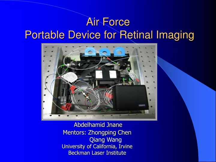
Air Force Portable Device for Retinal Imaging Abdelhamid Jnane Mentors: Zhongping Chen Qiang Wang University of California, Irvine Beckman Laser Institute
OUTLINE • Background • Goals • Device setup • Components • System parameters • Device component assembly • Sample OCT Images • Experimental design • Wiener filter implementation
Background • Field-deployable screening device to detect lesions of the retina • To facilitate early diagnostic of ocular laser induced injuries caused by laser weapons and laser guided aiming devices. • To reduce the risk of catastrophic failure of vision. • To ensure that flight personnel will conduct missions with full visual acuity.
Background • Replacement of the current photographic fundus imaging device • Standard procedure for evaluating ocular lesions, it provides only two-dimensional retinal imaging • The newly developed optical coherence tomography technology with integrated micro electro mechanical system (MEMS) • To provide a three-dimensional of retinal images’ surface
Background • The proposed field deployable imaging device will find many other applications • In ophthalmology clinical practice where evaluation and diagnosis of retinal health is very important • Anyone engaging in a potentially dangerous activity requiring superb visual performance
Goal • Designing a compact & portable OCT system • Features • Dimensions: 8” x 8” x 4” • Sensitivity of 99.3 db • High speed (20,000 A-lines/s ) • High resolution (12 m ) • Coherence length of 9.8mm at 2 kHz sweep rate • Testing our device in vivo animal and human subjects • Evaluating retinal injuries in hamster and rats • Filtering the noise that corrupted the source signal (ripples)
Device Setup Figure 1: Schematic of the FDOCT system: collimator; Atte., neutral density attenuator; D1 and D2, photodetectors.
Components • Collimator (OFR Inc., 1060 nm) • Gold mirror (Thorlabs Inc., ½”) • 2 circulators (Agiltron Inc., 1060 nm) • 70/30 2x2 couplers (AC Photonics Inc. 1060 nm) • 50/50 2x2 couplers (AC Photonics Inc. 1060 nm) • X stage (Newport Inc.) • Light source (Santec Inc., 1060 nm, 28 kHz) • Aluminum case (Hammond Manufacturing, 10.03” x 9.63” x 3.84”)
System Parameters • Imaging speed: 20 k A-lines/second • Power delivered to sample arm: 1.2 mw • Power delivered to reference arm: 0.4 mw
Device Hardware Non-compact OCT system Compact OCT system
Sample OCT Image • Human eye image
Experimental Design • In vivo animal clinical trial experiment will be conducted to test the effectiveness of the new device. • Imaging devices • Portable OCT system • Photographic fundus imaging system • Evaluation of images by ophthalmologists • Group 1: photographic fundus images only • Group 2: photographic fundus images and OCT images • Ophthalmologist evaluation compared to histology evaluation
Group A (5 Rats) • 23.6 mw, 0.25 s
Wiener Filter • The wiener filter is an adaptive filter. • It tailors itself to be the “best possible filter” for a given dataset. • Below is a simple version of the derivation for the wiener formula.
Wiener Filter • Standard equation to model a signal with noise: y [n] =x [n] +n [n] (1) • We want to pass this y [n] through a filter ‘h’ • To get back something that very closely matches our original signal x, ( x) • Design a filter that minimizes the difference between x and x. • minimizing the least mean square error between x and x [x − ˜x] 2 (2)
Wiener Filter • Since x is h*y, we have: [ x − h * y ] (3) • Expanding this expression and taking the Fourier transform of the expression to get the power spectra: • ∑(j) ( (Xj − HjYj))2 (4) • ∑(j) ((Xj − Hj (Xj + Nj))2 (5) • After simplification we get the following formula for H • H (f) = (|X (f) |)2/ (|X (f) |)2 + (|N (f) |)2 (6)
Spectral Reshaping • Small ripples in the light source spectrum caused by antireflection coating of the semiconductor optical amplifier • Ripples & other types of dispersions in the optical fiber components modulate the fringe contrast of the spectral interference signal Spectrum of light with ripple and side lobes
Spectra and Gaussian Fit from Glass Slide • Solid curve: • Spectrum determined from a single image • Dashed curve: • Gaussian fit to each spectrum
Coherence Envelopes Determined from Glass Slide • Dotted curve: Uncorrected response • Solid curve: • Corrected response
Design of Wiener Filter • Determine the envelope of the wavelength-dependent fringe contrast • Design a spectral shaping filter from the OCT spectral signals • Spectral interference signal can be rewritten as follows: • S j (k) = Se (k) *cos φ j(k) (1) • contrast envelope* fringe • where φ j(k) is the phase of the j-th fringe
Design of Wiener Filter • The ensemble average of spectral interference in j is expressed as • (Sj(k)^2)j = Se(k)^2 cos^2φ j(k)j • Simplified equation of the contrast envelope: • Se(k) =√(2/N*Σ(j)Sj(k)^2). • Substituting Se(k)into the following the Wiener filter: • W(k) =(Se(k)/(Se(k)2 +nc))*Gauss(k) • nc is a constant depending on the SNR of the detection system • Gauss(k) is a Gaussian window to reshape the spectrum to a Gaussian profile.
Implementation of Wiener Filter • SpecEnv[j] = A + B1*j + B2*j^2 + B3*j^3 + B4*j^4 + B5*j^5 + B6*j^6 + B7*j^7+ B8*j^8 • Where: A=23.84411; B1=0.95364; B2= -0.0062 ;B3=9.5098E 5; B4= -7.19185E7; B5=2.49286E-9; B6= -4.32256E-12; B7=3.66599E-15;B8=1.21285E-18 • GuassionEnv[j] = 100*exp(-(j-425.0)* (j-425.0)/240.0/240.0); • SpecReshape[j]=GuassionEnv[j]/(2.0*SpecEnv[j] +constant factor);
Axial PSF without Spectral Reshaping Single image of the glass mirror
Axial PSF with Spectral Reshaping Single image of the glass mirror
Conclusion • We have developed FDOCT device with 1m swept light source which has the following specifications: • Dimensions of 8” x 8” x 4”; • Sensitivity of 99.3 db; • High speed (20,000 A-lines/s); • High resolution (12 m); • Coherence length of 9.8mm at 2 kHz sweep rate.
Conclusion • We have also shown that FDOCT resolution can be improved by reducing the effects of the tails or side lobes by implementing the Wiener Filter algorithm to get a gaussian shape of spectral light source. • The algorithms we have used take advantage of the convolution property of Fourier transformation. Therefore, extensive computation that can slow the speed of the OCT is not necessary.
Progress • Prepare medication and supplies for animal study (anesthesia, eye-drops, heat pads, surgical instruments, etc.) • Set up portable OCT system • Optimize and calibrate portable OCT system • Order lab rats • Begin imaging rat, rabit and hamster retina • Design Wiener filter to reduce noise • Conduct the clinical trial experiment
Acknowledgements • Dr. Zhongping Chen • Dr. Qiang Wang • University of California, Irvine • Beckman Laser Institute • IM-SURE Program • Said Shokair • NSF