Download
1 / 26
260 likes | 363 Views
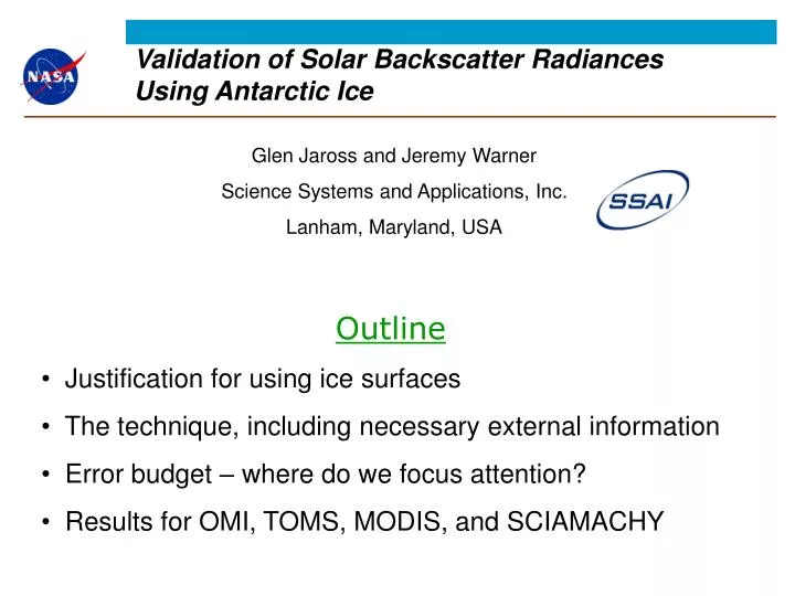
Validation of Solar Backscatter Radiances Using Antarctic Ice. Glen Jaross and Jeremy Warner Science Systems and Applications, Inc. Lanham, Maryland, USA. Outline Justification for using ice surfaces The technique, including necessary external information

E N D
Validation of Solar Backscatter Radiances Using Antarctic Ice Glen Jaross and Jeremy Warner Science Systems and Applications, Inc. Lanham, Maryland, USA • Outline • Justification for using ice surfaces • The technique, including necessary external information • Error budget – where do we focus attention? • Results for OMI, TOMS, MODIS, and SCIAMACHY
Cloud Fractions (λ-independent radiance errors) Cloud studies Energy balance and UV irradiance Cloud height: errors are directly proportional to cloud fraction (low cloud amounts) Gas vertical column amounts: Air Mass Factor errors directly related to cloud fraction. ( 3% - 5% column NO2 error per 5% cloud error; low cloud amounts) Aerosol Properties (λ-independent and λ-dependent radiance errors) 0.015 error in single-scatter albedo per 1% radiance error Optical Depth error 0.06-0.12 per 1%/100 nm λ-dependent radiance errors What products benefit most from scene-based calibration ?
Spectral fitting algorithms (e.g. DOAS) Insensitive to low-order-in-λ calibration errors Conversion from slant to vertical column still sensitive Gas abundances (slant column) Need knowledge of abundance to calculate expected radiances, but gas abundance depends upon calibration Limb scattering and Occultation Normalizing radiances at a reference height nearly eliminates sensitivity to underlying scene reflectance Most instruments do not have a nadir view Where is scene-based calibration less effective ?
Antarctica is a good radiance calibration target • High Reflectance • direct / diffuse TOA radiance ratio greatest • radiances least affected by clouds and aerosols • Low Aerosol Loading • Uniform Reflectance Over a Large Area • Highly Repeatable (stable) Reflectance R (Lambertian) > 0.95 TOMS Earth Probe 360 nm Reflectivity (1996) 90 % 100 %
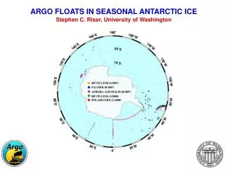
Data Selection Region Areas with Slope<0.005 radians • Region selected for • low surface slope • high reflectivity • uniformity TOMS Earth Probe 360 nm Reflectivity (1996) 90 % 100 %
cloud= 5 at 440 mb GOME (Jan. 2000) nadir-scene 357 mn 775 nm albedo ratio Modeled nadir-scene 357 mn 775 nm albedo ratio Are clouds an issue ? Either the cloud model is wrong, or … Clouds are statisticallyunimportant
Time Dependence of radiometric calibration TOMS Earth Probe 360 nm TOMS Nimbus 7 380 nm Greenland OMI (Aura) 360 nm Antarctica • Seasonal Cycle: • Neglecting terrain height variations • Surface reflectance non-uniformity
1996 1997 1996 1997 Comparison between sensors 360 nm GOME / TOMS-EP Radiance Ratio Very early GOME calibration Comparisons need not be over the same time period 331 / 360 nm
Validation of Absolute Radiometry • Develop a 2 steradian directional reflectance (BRDF) model for the Antarctic surface; independent of wavelength. • Combine BRDF with surface measurements of total hemispheric reflectance measurements; wavelength-dependent • Create a look-up table of sun-normalized Top-of-the-Atmosphere (TOA) radiances for all satellite observing conditions using a radiative transfer model • Process sensor sun-normalized radiance data from a region of Antarctica chosen for uniformity and low surface slope • Compute ratio between each measurement and table entries; average results
Surface properties based upon reflectance measurements by Warren et al. = 600 nm Sol. ZA = 80 Spectral Albedo Measuremnts at South Pole, 1986 Warren et al. Reflectance anisotropy derived from 1986-1992 data BRDF probably the same: 300-800 nm BRDF derived from parameterization of measured reflectance anisotropy
New Reflectance Measurements by Warren et al. • Measurements at Dome C, 2003-2005 • Spectral BRDF of surface 0.35 – 2.5 m • Solar Zenith Angles 52 - 87 • Measure spectral transmission of sunlight into snow • Measurements used for inputs to models for effect of clouds on TOA radiances • Funded by U.S. National Science Foundation and CNES • will support radiometric validation for SPOT4 (Laboratoire de Glaciologie et Géophysique de l’Environnement) • data not yet published
Error Budget Surface BRDF model represents single largest error source
SolZA=40 SolZA=50 SolZA=60 SolZA=85 Surface BRDF model vs. Solar Zenith Angle
Non-Lambertian / Lambertian Radiance Ratio Lambertian Non-Lambertian BRDF is most important at longer wavelengths BRDF plays bigger role as diffuse / direct ratio decreases Simulated Nadir-scene albedos Solar Zenith Angle = 75 Column Ozone = 325 DU
OMI Results OMI L1b Data: 7 Dec – 4 Jan, 2004 • Perfect model would yield flat SolZA dependence • Perfect calibration would yield values = 1 at all wavelengths • Plot suggests probable radiative transfer errors • surface BRDF model • treatment of atmosphere • We believe that results obtained below SolZA = 70 fall within our 2.2% uncertainty estimate
OMI Full spectral range ice radiance results 83 < SolZA < 86 62 < SolZA < 68 Flat spectral result gives us confidence that result is resonable Spectral dependence is not realistic – consistent with BRDF error Apparent error increases at long as predicted
Shadowing Errors From Radarsat-1 Large scale structures (snow dunes) not captured by ground characterizations
Simple linear shadow model for testing errors Tune barrier height and separation to yield flattest SolZA dependence in data
Shadow study using MODIS / Aqua Comparison to RTM, without correction Consistent with ~2% uncertainty estimate Comparison to RTM, with shadow correction
MODIS / Aqua TOMS / EP OMI / Aura O2O2 Absorption Comparison between MODIS, OMI, TOMS and model radiances RTM handles ozone poorly at < 330 nm RTM does not include Ring Effect or O2-O2 abs.
Preliminary SCIAMACHY Results SCIAMACHY Level 1b ( v5.04 ) 18 – 24 Dec., 2004 Provided by R. van Hees, SRON } Comparison with RTM over Sahara (from G. Tilstra, KNMI) Ozone Absorption ignored
Summary • Model calculations of TOA radiances over Antarctica are good to approximately 2% at low solar zenith angles (i.e. near Dec. 21) • Radiometric characteristics of nadir-viewing sensors can be validated from ~330 nm to ~750 nm • Wavelength-to-wavelength radiometry is better than 2%, but not useful for absorption spectroscopy • We derive the following sensor calibration errors (preliminary) OMI / Aura: -2.5% (330 < < 500 nm) MODIS / Aqua : -0.5% ( < 500 nm) TOMS / Earth Probe : 0% (331 nm), -1% (360 nm) • Future Work : • Evaluate more sensors. SCIAMACHY, GOME 2 ? • Refine BRDF for improved performance at high SolZA and SatZA
X-track dependence is mostly Lambertian near SolZA = 50 BRDF surface slices at 67 Results near 50 are least affected by BRDF errors
OMI radiances compared directly to MODIS / Aqua band 3 MODIS OMI Same time and geographic location MODIS has broad bandwidth (459 < < 479 nm) which includes O2-O2 absorption
Existing parameterization from • Warren et al. • J. Geophys. Res., 103, 1998 • s 50 o 67 all • Extrapolate function for use at s > 50 • Invoke reciprocity ( s > 67 o<67 ) • Fill remaining “hole” ( s < 67 o<67 ) • assume s2dependence for all o <67 • derive (s=0) at each o <67from a quadratic parameterization of observed scattering phase fn. (Warren, et al., ibid) (s= 0) - 67 s + 67 o Developed a 2 steradian BRDF model