Download
1 / 104
1.07k likes | 1.37k Views
Practicum on Solar Radio Instrumentation. Tim Bastian (NRAO) Mark McConnell (UNH). Why observe the Sun at radio wavelengths?. Solar emission at radio wavelengths provides unique diagnostics for physical parameters of interest and their evolution in time and space

E N D
Practicum on Solar Radio Instrumentation Tim Bastian (NRAO) Mark McConnell (UNH) T. Bastian, Second SPD Summer School on High Energy Solar Physics
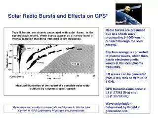
Why observe the Sun at radio wavelengths? • Solar emission at radio wavelengths provides unique diagnostics for physical parameters of interest and their evolution in time and space - thermal free-free - nonthermal gyrosynchrotron - thermal gyroresonance - plasma radiation - exotica B(r), T(r,t), f(r,p,q,t) • Radio emission probes both optically thick and optically thin regimes • Radio emission probes both active and quiet phenomena • Radio emission probes all layers of the solar atmosphere from the temperature minimum to the interplanetary medium - temperature minimum to middle corona (ground) - middle corona to IPM (space) • Radio waves can be observed with high angular (arcsec), temporal (ms), and spectral resolution (kHz) T. Bastian, Second SPD Summer School on High Energy Solar Physics
Preliminaries • No RF lab at NRH • No easy way to transport receivers and test equipment to UNH • However, UNH has a Small Radio Telescope (SRT) Therefore, we’ll do things in two parts today: • I will present basic concepts relevant to radio instrumentation (science issues and data analysis are deferred to my other two lectures) • We will then use the UNH SRT remotely to observe the Sun (Mark McConnell) T. Bastian, Second SPD Summer School on High Energy Solar Physics
Practicum on Solar Radio Instrumentation • The radio spectrum and its uses • Terminology and some important concepts • Overview of instrumentation on the ground and space - antennas and receivers - single dish observing - interferometry - Fourier synthesis imaging • Examples - radiometry and polarimetry - broadband spectroscopy - interferometry - Fourier synthesis imaging • Using the UNH SRT T. Bastian, Second SPD Summer School on High Energy Solar Physics
T. Bastian, Second SPD Summer School on High Energy Solar Physics
tbastian@nrao.edu T. Bastian, Second SPD Summer School on High Energy Solar Physics
The electromagnetic spectrum T. Bastian, Second SPD Summer School on High Energy Solar Physics
The electromagnetic spectrum ground radio space T. Bastian, Second SPD Summer School on High Energy Solar Physics
Radio Frequency Allocations T. Bastian, Second SPD Summer School on High Energy Solar Physics
Radio Frequency Allocations T. Bastian, Second SPD Summer School on High Energy Solar Physics
Radio Frequency Allocations T. Bastian, Second SPD Summer School on High Energy Solar Physics
Radio Frequency Interference SRT T. Bastian, Second SPD Summer School on High Energy Solar Physics
Antennas and Arrays T. Bastian, Second SPD Summer School on High Energy Solar Physics
Variable Manipulation Elements Variable Manipulation Elements Variable Conversion Element Data Presentation Element Data Transmission Element Primary Sensing Element Measured Medium Observer SIGNAL Variable Conversion Element Sampler Signal Processor Feed Receiver Radio Telescope Functional Blocks GUI T. Bastian, Second SPD Summer School on High Energy Solar Physics
Purpose of the Antenna 1.Collect of a tiny bit of radiation for use in the measurement process. Collecting Area 2.Spatial filtering Directionality or Pointing 3.Convert EM flux density to an electrical signal Feed Point to extract the collected energy – energy conversion process 4. Spectral Filtering Will operate over a specific range or “spectral band” of radiation T. Bastian, Second SPD Summer School on High Energy Solar Physics
Antennas and Arrays Antennas are structures designed to collect or transmit radio waves. Antenna designs constitute a nearly uncountable set… T. Bastian, Second SPD Summer School on High Energy Solar Physics
Antennas and Arrays Ulysses/URAP WIND/WAVES T. Bastian, Second SPD Summer School on High Energy Solar Physics
Simplest case: Hertzian dipole (D<<l) D T. Bastian, Second SPD Summer School on High Energy Solar Physics
Antennas and Arrays The design of a particular antenna must be matched to the problem at hand. Low frequency antennas (n< few x 100 MHz) may employ some variant of a dipole or phased dipole array since their effective area is proportional to l2. At higher frequencies, signal is collected with a mirror that most often takes the form of a parabolic reflector of diameter D >> l. This focuses radiation on a feed that couples the radiation to electronics that amplify the signal. For our purposes, we will consider a conventional parabolic antenna in order to illustrate some basic concepts before discussing interferometry and Fourier synthesis imaging (which is basically what RHESSI does). T. Bastian, Second SPD Summer School on High Energy Solar Physics
Antennas and Arrays Let’s use a parabolic single dish to illustrate some basic points. Resolution Antenna response function Antenna gain T. Bastian, Second SPD Summer School on High Energy Solar Physics
Antennas and Arrays a q q D D sinq b q Ray b travels a distance D sinq farther than ray a. The two rays therefore arrive at the focus with a phase difference of Df= D sinq/l wavelengths, or Dq/lwhen qis small. When this difference is plus or minus l/2, the two rays are completely out of phase and their contributions cancel. The angleqat which this happens characterizes the angular resolution of the aperture. T. Bastian, Second SPD Summer School on High Energy Solar Physics
The Standard Parabolic Antenna Response T. Bastian, Second SPD Summer School on High Energy Solar Physics
Antennas and Arrays Effective collecting area Aeff(n,q,f) m2 On-axis response: Ao = hA A = physical area h = antenna efficiency Normalized antenna pattern: Pn(n,q,f) = Aeff(n,q,f)/Ao T. Bastian, Second SPD Summer School on High Energy Solar Physics
Antennas and Arrays The beam solid angle at frequency n is then given by The antenna gain is given as the ratio of the beam solid angle to that of an isotropic antenna (or 4p): Sometimes measured as a ratio to an idealized isotropic antenna in dBi. Hertzian (short) dipole: G = 1.5 = 1.76 dBi VLA antenna (20 cm): G = 1.3x105 = 51 dBi Using the fundamental relation thatl2=Ao WA, T. Bastian, Second SPD Summer School on High Energy Solar Physics
u (, ) = aperture illumination = Electric field distribution across the aperture (, ) = aperture coordinates FT u(,) = far-field electric field ( , ) = direction relative to “optical axis” of telescope |u ()|2 Aperture-Beam Fourier Transform Relationship |u ()|2 FT FT T. Bastian, Second SPD Summer School on High Energy Solar Physics
Antennas and Arrays The solid angle of the main lobe of the antenna power pattern is Now the flux density from a source on the sky with a brightness distribution (specific intensity) B(q,f) erg cm-2 s-1 Hz-1 ster-1 is If the normalized power pattern of an antenna isPn(q,f) the flux density within the telescope beam is T. Bastian, Second SPD Summer School on High Energy Solar Physics
Antennas and Arrays If the angular size of the source is very small compared to the main lobe of the beam, Pn= 1 over the source and the measured flux density is the true flux density. If the source has an angular extent greater than the main beam, the measured flux density must be less than the true value. For an extended source of constant brightness Note thatBo=Sn/WM– flux density per beam is thus a measure of the brightness or the specific intensity! One needs a small beam size – a large dish - to make meaningful measurements of the specific intensity in an extended source. T. Bastian, Second SPD Summer School on High Energy Solar Physics
Units Source flux: W m-2or ergs cm-2 s-1 Flux density: W m-2 Hz-1 or ergs cm-2 s-1 Hz-1 1 Jansky = 10-26 W m-2 Hz-1 1 solar flux unit = 104 Jy Specific intensity: W m-2 Hz-1 ster-1or ergs cm-2 s-1 Hz-1 ster-1 Jy/beam SFU/beam Brightness Temperature (K) T. Bastian, Second SPD Summer School on High Energy Solar Physics
Brightness Temperature Thermal radiation is radiation emitted by matter in thermal equilibrium; i.e., material that can be characterized by a macroscopic temperature T. Material in thermal equilibrium that is optically thick is referred to as a black body. The specific intensity of a black body is described by the Planck function: Which is itself characterized by the temperature of the body, T. T. Bastian, Second SPD Summer School on High Energy Solar Physics
Brightness Temperature Planck function T. Bastian, Second SPD Summer School on High Energy Solar Physics
Brightness Temperature Note that when it simplifies to the Rayleigh-Jeans Law. It is useful to now introduce the concept of brightness temperature TB, which is defined by T. Bastian, Second SPD Summer School on High Energy Solar Physics
Variable Manipulation Elements Variable Manipulation Elements Variable Conversion Element Data Presentation Element Data Transmission Element Primary Sensing Element Measured Medium Observer SIGNAL Variable Conversion Element Sampler Signal Processor Feed Receiver Radio Telescope Functional Blocks GUI T. Bastian, Second SPD Summer School on High Energy Solar Physics
Heterodyne Detection In its most basic form, the heterodyne receiver consists of a radio frequency (RF) section, which performs signal processing functions such asamplification and spectral filtering in the frequency band of the incoming waves (the RF band), and an intermediate frequency (IF) section which performs additional processing functions but usually at a much lower frequency (the IF band). T. Bastian, Second SPD Summer School on High Energy Solar Physics
RF to IF LSB USB Response n IF LO RF=LO-IF RF=LO+IF T. Bastian, Second SPD Summer School on High Energy Solar Physics
A Few Performance Parameters Noise – the uncertainty in the output signal. Ideally, this noise consists of only statistical fluctuations. Linearity – the degree of which the output signal is proportional to the input photons that are collected. Dynamic range – the maximum variation in the radiation power over which the detector output represents the photon flux. Number and size of pixels – the number of picture elements that the detector can record simultaneously and the physical size of each element in the detector. Time response – the minimum interval of time over which the detector can distinguish changes in the photon arrival rate. Spectral response – the total wavelength or frequency range over which the photons can be detected with reasonable efficiency. T. Bastian, Second SPD Summer School on High Energy Solar Physics
System and Antenna Temperature The power output from a receiver can be expressed in terms of an equivalent temperature: This can, in turn, be separated into various contributions due to the source, components of the system (feed, receiver, transmission lines, …) and other extraneous sources: The contribution of a source S to Toutis referred to as the antenna temperature, with: T. Bastian, Second SPD Summer School on High Energy Solar Physics
Example • A typical system temperature for a modern radio telescope is 30 K. What is the antenna temperature of a 1 Jy source observed by a 20 m antenna with an aperture efficiency of 0.6? Ans: • What if we point at the Sun and observe at a wavelength of 20 cm, for which the solar flux density ranges is ~100 SFU? Ans: T. Bastian, Second SPD Summer School on High Energy Solar Physics
Solar Radio Observations • Total flux monitoring • Dynamic Spectroscopy Some Examples T. Bastian, Second SPD Summer School on High Energy Solar Physics
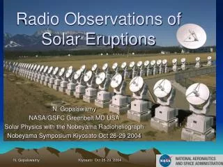
Solar Radio Observations Nobeyama Polarimeters (1,2,3.75, 9.4, 17, 35, and 80 GHz) T. Bastian, Second SPD Summer School on High Energy Solar Physics
Solar Radio Observations T. Bastian, Second SPD Summer School on High Energy Solar Physics
Solar Radio Observations T. Bastian, Second SPD Summer School on High Energy Solar Physics
Solar Radio Observations Green Bank Solar Radio Burst Spectrometer T. Bastian, Second SPD Summer School on High Energy Solar Physics
Solar Radio Observations T. Bastian, Second SPD Summer School on High Energy Solar Physics
Solar Radio Observations T. Bastian, Second SPD Summer School on High Energy Solar Physics
Solar Radio Observations T. Bastian, Second SPD Summer School on High Energy Solar Physics
Solar Radio Observations ETH instruments near Bleien, Switzerland T. Bastian, Second SPD Summer School on High Energy Solar Physics
Solar Radio Observations T. Bastian, Second SPD Summer School on High Energy Solar Physics Isliker & Benz 1994
Solar Radio Observations Solar Radio Burst Locator Owens Valley, CA T. Bastian, Second SPD Summer School on High Energy Solar Physics
Solar Radio Observations T. Bastian, Second SPD Summer School on High Energy Solar Physics
Solar Radio Observations Wind Waves plus Culgoora T. Bastian, Second SPD Summer School on High Energy Solar Physics Dulk et al. 2001