Download
1 / 39
521 likes | 886 Views
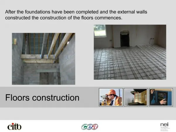
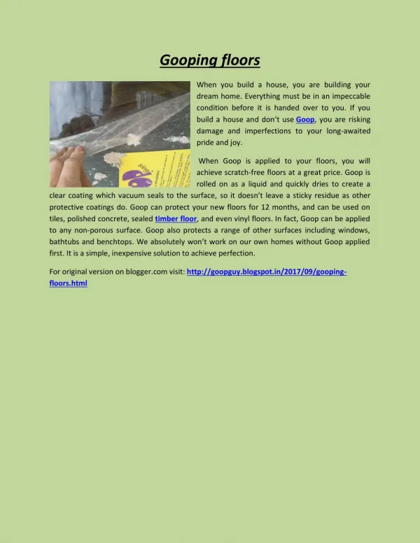
UPPER FLOORS. TIMBER AND CONCRETE. FUNCTIONS OF AN UPPER FLOOR. Functions: Support imposed loads Not deflect under load Strength and stability Provide restraint for external walls Fire resistance (30 minutes) Limit sound transmission Principle

E N D
UPPER FLOORS TIMBER AND CONCRETE
FUNCTIONS OF AN UPPER FLOOR • Functions: • Support imposed loads • Not deflect under load • Strength and stability • Provide restraint for external walls • Fire resistance (30 minutes) • Limit sound transmission • Principle • Large timbers known as joists span from wall to wall on which a decking is placed to form a level floor
PLACEMENT OF JOISTS • Joists are normally placed in position when blockwork has reached the required level • Joists are spaced at 400mm c/c • Rule of thumb calculation for depth of joists • Span of joist in mm + 50mm 24 • Example 4m span • 4000/24 + 50 = 217mm use a 225 joist
CONSTRUCTION DETAILS • Secured to wall at ends • Built in • 90mm min. Bearing • End grain treated with preservative • Mortar packed solidly around joist Note end of joist is tapered
CONSTRUCTION DETAILS • Secured to wall • Galvanised steel joist hanger built into wall
CONSTRUCTION DETAILS • Secured to parallel walls • Bridging to prevent twist
INTERNAL WALLS • The ends of the joists may be rested on a wall plate on top of an internal partition although in practice the wall plate is often omitted This provides a sound, uniform bearing with maximum distribution of the loads. • Where joists from either side meet on a load bearing wall, they are usually placed side by side and nailed to each other with laps of at least 150 mm
BRIDGING / STRUTTING • As the span of the joists increases ( above 3 m ) there is a tendency for the joists to twist which could cause damage to the ceiling below. • To prevent this twisting, strutting is usually included if the span of the floor exceeds 2.5 m. • There are two forms of strutting, • HERRINGBONE STRUTTING • SOLID STRUTTING
SOILD BRIDGING / STRUTTING Bridging should be in a straight line • Used to to tie joists together so that: • The load is distributed over a number joists • To prevent joists from twisting • Lines of bridging should be positioned no greater than 1350mm apart
HERRINGBONE BRIDGING / STRUTTING • Herringbone strutting is made up of approx 35 x 35 mm timbers with their ends cut at an angle and nailed together where they intersect and to the top of one joist and the bottom of the next. • The space between the first and last joist and the adjoining wall is wedged with folding wedges to take the thrust of the strutting.
OPENINGS IN UPPER FLOORS stairwell ope Doubled or thicker joists joist hanger internal load bearing wall
OPENINGS IN UPPER FLOORS • The trimming joist and the trimmer joist are increased in thickness by 25 mm from 225 x 50 mm to 225x 75 mm because of the extra weight they have to carry. • The trimmed joist has no extra weight to bear so its dimensions are unaltered at 225 x 50 mm.
OPENINGS IN UPPER FLOORS • Floor joists around openings such as stair wells and fire hearths must be self supporting. • In order to achieve this the sections of timber around the opening must be bigger to cope with the extra stresses. • In having to maintain a level floor and ceiling the increases must be in the width of the joists and is usually 25 mm. • There are a number of jointing methods that can be used between the TRIMMING, the TRIMMER and the TRIMMED joists. • Strong and soundly constructed joints are required between the trimming members, and the tusk tennon joint is often advocated for its strength.
TUSK TENON JOINT • Used to join a trimmer joist to a trimming joist
COMMON JOINTS USED IN FLOOR JOISTS • Joints used between trimmed joists and trimmer joist • Housed joint and dovetailed notch while very good would be very labour intensive thus costly
COMMON JOINTS USED IN FLOOR JOISTS • Two most commonly used methods of forming the joint between the trimmed joists and the trimmer • Note the larger section of timber used for the trimming joist and the trimmer joist
TYING FLOORS TO EXTERNAL WALLS • It necessary to strap floor joist to external walls for stability • L Straps to be 30X5mm galvanised steel • Straps to be located at 2m c/c max • Straps to tie in at least 3 joists with bridging between joists under strap • Straps are placed as work is in progress
JOISTS RUNNING PERPENDICULAR TO PARTY WALL • Where possible joists should always run parallel to party wall • Joists should never be set into party wall
JOIST RUNNING PERPENDICULAR TO PARTY WALL • Joist hangers may be used as an alternative to setting the ends of joists into a party wall
SOUNDPROOFING UPPER FLOORS • Sound travels in two ways • AIR BORNESOUND • IMPACT SOUND • In order to reduce the transmission of sound between upper and ground floors a FLOATING FLOOR must be provided.
SOUNDPROOFING UPPER FLOORS • To reduce the transmission of Air-borne sound the density of the floor will need to be increased. This can be achieved by including 50-75 mm of sand pugging between the joists. The weight of the sand should be carried on the joists ( and not on the ceiling slab ) by fixing a 44 x 20 mm batten to the bottom of the joist. A strip of 12 mm ply can be fitted between the joists on top of which the sand is placed. • The floating floor gets its name from the actual construction of the floor. A 50 mm resilient quilt is laid over the top of the joists. 50 x 50 mm battens are laid on top of the quilt directly over the joists and the floor boards are nailed to the battens. • The battens are not nailed to the joists. This in effect isolates the floor surface from the ceiling below - thus reducing the transmission of Impact sound.
CONCRETE UPPER FLOORS • Two methods; • BOTH METHODS WILL REQUIRE A FINISH SCREED • BOTH METHODS REQUIRE EXTRA SUPPORT • I.E. BLOCK ON FLAT AT GROUND FLOOR LEVEL • Pre-cast / hollow core concrete slabs • Easy to use • Relatively lightweight ( compared to solid) • Very fast to install • May require drilling to accommodate services • Solid poured floor • Slow to install • A lot of support required • Easier to accommodate services • Better thermal and sound insulation
PRE-CAST SLABS • Concrete screed to be poured over slabs incorporating all services
FLOOR FINISHES • Functions: • Appearance / colour / texture • Durability / resistance • Hygiene / ease of cleaning • Vinyls • Carpets • Tiles • Timber