Download
1 / 32
430 likes | 650 Views
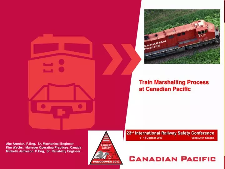
Train Marshalling Process at Canadian Pacific. Abe Aronian, P.Eng , Sr. Mechanical Engineer Kim Wachs, Manager Operating Practices, Canada Michelle Jamieson, P.Eng , Sr. Reliability Engineer. Train marshalling – why is it needed?.

E N D
Train Marshalling Process at Canadian Pacific Abe Aronian, P.Eng, Sr. Mechanical EngineerKim Wachs, Manager Operating Practices, CanadaMichelle Jamieson, P.Eng, Sr. Reliability Engineer
Train marshalling – why is it needed? Train marshallingwas very basic and almost non-existent at the early stages of railroading. Trains changed immensely since those early days: 1) trains got longer 2) trains got heavier 3) different types of freight cars (length, tare weight, capacity, EOC) 4) Advanced Traction locomotives (heavier pull and braking) 5) Distributed power (locomotives) throughout the train Different track profiles 1) heavy ascending grades 2) heavy descending grades 3) undulating track profiles 4) high degree curves 5) combinations of all of the above
Train marshalling & train dynamics Virtually inseparable Train Dynamics is the understanding of the dynamic motion and forces resulting from train handling, train make-up, grade and curve combinations, which influence the interaction of vehicles in a train. Train Dynamics needs to be understood and considered for safer train operations. Complexities of non-uniform trains can only be safely evaluated through solid understanding of Train Dynamics theories and considerations The answer to any derailment caused by non-obvious track or vehicle defects can mostly be explained through Train Dynamics Train Dynamics begins by considering all potential forces on a train.
Forces on the Track – Vertical & Lateral To Keep Wheel on Rail: Vertical Forces > Lateral Forces VERTICAL FORCES: caused by load of car and undulating track LATERAL wheel against rail) , coupler angling and truck warping during curving
High In-Train Forces on Curved Track String-lining . Too much head-end power pulling on empty cars at the head-end of train Jack-Knifing : head-end retardation too abrupt, causing a run-in of slack of heavy cars on empty cars (or drawbar mismatched cars)
and Why It Is So Important - 1 Absolutely critical not to have Lateral Force above 80% of Vertical force, or L/V < 0.82 for safe conditions High Lateral Force will push the wheel flange up against the rail and could lift it up when insufficient Vertical Force exists to hold it down. Wheel lift and derailment will occur.
L/V Ratio and Why It Is So Important Source: Rail Sciences Inc. Presentation2004 Wheel/Rail Interface Seminar High Lateral Forces can roll the rail over (causing wheel set to drop between rails and derail. This condition is specially prevalent for poorly restrained rail conditions.
What about worn wheel/rail scenario ? The lateral load “L” is applied at a height “H” above the base of the rail and the vertical wheel load “V” is applied at a distance “B” from the field side corner. This relationship of L/V is equivalent to the B/H ratio of the rail. Rail roll over will occur when L/V > B/H. High rail gauge face wear will shift the V load position and reduce the B dimension, and reduce the B/H ratio.
How are Lateral Forces Generated ?What Happens As Car Enters a Curve ? Outer Wheel has a longer distance to travel than the Inner Wheel. It moves closer to the wheel flange (larger diameter) and starts flanging with the rail head – Generating a LATERAL FORCE. The tighter the curve, then Higher the Lateral Force generated at the wheel flanges.
What Else Generates Lateral Forces ?Coupling Angles and Drawbar Force The Lateral force generated by coupling angle is in addition to the lateral force resulting from the flanging of the wheel with rail on a curve. It is important to keep cars with equivalent lengths coupled together and not mix short/long cars in train Two cars of different lengths (with different coupler lengths) negotiating an 8 degree curve with a drawbar force of 100,000 lbs. The car with the longer coupler will generate a higher LATERAL force due to the larger angle the coupler would take on the curve. In this case, it will result in a combined lateral force of 15,300 lbs. at the leading truck, OR AN ADDITIONAL 3,800 LBS OF LATERAL FORCE AT EACH WHEEL.
How Much Drawbar Force Can High - Horse Power Locomotives Generate ? HIGH FORCES - 180,000 lbs. in Throttle 8 and 98,000 lbs. in DB8 What happens with TWO units coupled together ?
What Happens to Empty Spine Cars Under Buff ? L/V approaches 1.0 very quickly
Typical Loaded Car L/V Ratio Safe on Sharp Curves even with high in-train forces
L/V Ratio for long/short car combination Long/short car combinations, even though partially-loaded, will reach L/V ratio of 1.0 when draft forces approach 300,000 lbs. and buff forces get to 200,000 lbs. on curves of 10 degrees and higher.
Empty Cars in Train on 10 Degree Curves High L/V for Buff Forces exceeding 200,000 lbs. High L/V for Draft Forces exceeding 300,000 lbs. Similar length cars coupled together can tolerate higher in-train forces.
High Drawbar Forces with Head-End Power We saw how important it is to keep the in-train forces as low as possible. What to do to lower them ? Source: Long Train/Track Interaction Presentation, by. Dr. Jude Igwemezie, RAC Conference October 2010.
Distribute The Power For Lower In-Train Forces (Multiple-Remotes) Source: Long Train/Track Interaction Presentation, by. Dr. Jude Igwemezie, RAC Conference October 2010.
Lateral force detector site Detector situated on the Mountain Subdivision in British Columbia, 2.4% ascending grade, 5 degree curve. Multiple passes of various train designs show that the longer trains, set up with Multiple Remote locomotives, produce lower lateral forces for 14,000 ft. Intermodal trains, compared to single-remote 7,000 ft. trains.
Potash train progression Potash train make-up has registered productivity gains up to 37% since 2008. Lateral forces for such a train design are actually lower than a single-remote 112-car grain train.
Coal train progression 152-car train proven reliable year-round model, fully utilizing 4-locomotive haulage capacity and registering productivity gains of 23% since 2008.
Intermodal train progression Intermodal trains evolved in length and DP set up since their concept was modular. A long 14,000 ft. train became a series of short 4,500 train sections coupled together by locomotives distributed throughout the train. Multiple-remote set-up kept in-train forces (buff and draft) within acceptable limits and also reduced the lateral forces for acceptable L/V levels on some very light cars.
TrAM (TRAIN AREA MARSHALLING) - WHAT IT IS AND WHAT IT DOES Since 2003 The “physics” of train marshallingis relatively straightforward (take care of the excessive in-train forces and high L/V ratio). Their application to real train operation is very complex, as there are a variety of track profiles, vehicle types and train configurations that need to be taken into consideration. Prior to TrAM, CP’s train marshalling rules took into account only the extreme conditions (track and train) and applied the same rules across the entire network,. The primary considerations for the Rules designed to keep in-train buff and draft forces to acceptable levels (L/V ratio of 0.82 or lower) under a normal range of train handling and operating conditions, remained unchanged, however, they became territory-specific and applied differently based on the severity of track profile, train make-up and vehicle characteristics. For that reason, the CP network was divided into 5 “Areas” (Area 1 through Area 5) for the purposes of train marshalling. The division of the network was based on track profile, including characteristics such as grade, curvature, and undulations. Area 1 is the least restrictive, while Area 5 is considered the most restrictive. Typical physical characteristics of each Area are shown in the following table
Draft & buff forces Draft forces – must be evaluated behind each locomotive group in the train. The system must flag those locations in train where maximum allowable draft forces are exceeded. Draft Forces must be considered to prevent train separations (broken knuckle, broken drawbar) caused by excessive draft forces, and reduce excessive forces on the track structure. For High Adhesion AC locomotives, the maximum combined Tractive Effort (number of driving axles) must always be considered not to exceed yield strength of vehicles and track. Buff forces – must be evaluated for positions ahead of each remote locomotive group. The system must flag those locations in train where maximum allowable buff forces are exceeded.Buff Forces must be considered to prevent excessive forces on the track (Dynamic Braking) and to prevent pushing on very light cars (jack-knifing).
Trailing tonnage & threshold tonnage Trailing Car Tonnage – Applies to Mixed trains. Trailing tonnage restrictions are applicable to light/empty cars. Trailing Tonnage needs to be considered to avoid high L/V ratios.. There are separate trailing tonnage requirements in each TrAM area for the same car, as an empty car could accommodate higher trailing tonnage in a less restrictive Area (such as Area 1). Threshold Tonnage – Maximum train tonnage that can be handled without the possibility of causing a trailing car tonnage violation.
Long car & short car combinations Long Car & Short Car Combinations - For long cars the length of the adjoining car is important to arrive at a "car length factor" that will be used when determining the maximum trailing tonnage for that car combination. String of cars in uniform length would handle a higher amount of trailing tonnage.
Remote zone Remote Zone – this is the combined weight of a group of cars ahead of each Remote locomotive position in a mixed train. The number of the group of cars depends on number of remote locomotives at that location. In order to avoid excessive buff forces on empty/lightly-loaded cars, the Remote Zone must meet minimum weight requirements for this position in the train. The Remote Zone is the most restrictive portion of a Mixed DP Train.
Other considerations Ascending Grade Weight Zone – applies on ascending grades. As train tonnage increases, surpassing the Threshold tonnage, coupled to conditions of high number of driving axles on the head-end (high Adhesion locomotives), it is essential to set the head-end 10 to 15 cars be loaded to a certain weight, in order to avoid string-lining to occur. Maximum train length to last remote locomotive – this distance is important to ensures that in situations of loss of radio DP communication between the controlling locomotive and the last remote locomotive, straight-away brake pipe reduction will still cause the remote locomotive to idle down Dynamic brakes – these rules are required to limit the amount of buff forces grouped together in one spot (head-end for Conventional trains). In cases for DP trains, the placement of Remotes need to be such that DB efforts between Lead and Remotes are not additive, causing excessive buff forces (Jack-knifing).When such conditions exist, the system will require a reduced DB setting which must not be exceeded during train handling.
Cushion drawbars on conventional trains - split Service ---- 30 EOCs very low % for 100K and above slack action 50 EOC close to 1% chance of 100K or above slack action- Full Service ------ 30 EOC 0.5% chance of 100K or above slack action 50 EOC over 1% chance of 100K or above slack action
DP Trains with cushion drawbars simulation results of trains ranging from 30 to 70 cushion drawbars coupled together being brought to a stop using Full Service brake application over the undulating track. the percentage of slack forces exceeding 100 klbs. of buff is higher for the train with 70 cushion drawbars compared to the one with 30 cushion drawbars.
Too many eoc cars – what to do (Source: TUV Rheinland RSI Rail Sciences)
Train marshalling considerations - a dozen + Car types Car lengths Adjacent car lengths Car weights Adjacent car weights Track grades (ascending, descending, undulating) Track curvature (tight curves, combined curves) Cars with cushion drawbars Locomotive capabilities (tractive effort and Dynamic Brake) Type of train (mixed, bulk, intermodal/uniform, DP) Train weight Train length Destination blocking