Download
1 / 21
210 likes | 323 Views
Index: Abstractions The Op-Amp Abstraction The 3.5 mm Jack and Line Out A Simple LED Driver The receiver Fourier Expansions Why Filters? The Butterworth Filter. Abstractions: What is an abstraction?

E N D
Index: • Abstractions • The Op-Amp Abstraction • The 3.5 mm Jack and Line Out • A Simple LED Driver • The receiver • Fourier Expansions • Why Filters? • The Butterworth Filter. OPTOCOUSTICS
Abstractions: • What is an abstraction? • Abstraction is the process of taking away or removing characteristics from something to reduce it to some set of essential characteristics. • e.g. A football is a “ball” • Why am I concerned? • It is a powerful tool • Abstractions as in electrical engineering. • Branch into two domains: • Analog and Digital OPTOCOUSTICS
printf( ); OPTOCOUSTICS
Abstractions (Continued…) The Digital Domain The Analog Domain OPTOCOUSTICS
The Op-Amp Abstraction: • What is an Op-Amp? • Scary Monster…………..but we can abstract its functioning!...... • Op-Amp abstraction…… • Treat the Op-Amp as a black box ( remember printf ). OPTOCOUSTICS
The Op-Amp Abstraction (Continued…..) • What is the abstraction about? • A few rules to be remembered…… • No current flows into the inputs…..(The inputs behave as infinite resistances) • The output port offers a weak resistance. • If output is connected to the inverting terminal through any passive device, the device is said to be (–)ve feedback and the input terminals will be at the same potential (Virtually short circuited). OPTOCOUSTICS
The Op-Amp Abstraction (Continued…..) • 4 Op-Amps on a single IC • Both single and split supply supported • Cheap!! LM324 OPTOCOUSTICS
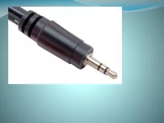
3.5 mm Jacks and Line-Out • Line out characteristics: • Max Peak-Peak voltage of 2 Volts • Referenced at -10dBV (300mv approx.) • Intended to directly drive impedances of 10kΩ • Courtesy: Wikipedia® OPTOCOUSTICS
This is the most basic structure. Further design decisions depend on your implementation A Simple LED Driver OPTOCOUSTICS
The Receiver: This is the most basic structure. Further design decisions depend on your implementation OPTOCOUSTICS
Fourier Expansions: • Remember vector decomposition. • You can generate any vector in ℝ3 by simply choosing different values for x,y and z i.e. the coefficients of the basis vectors , , OPTOCOUSTICS
Similarly, represent a signal as a sum of sinusoids – weighted by different coefficients. • That is to say, just as any vector can be represented by the 3 unit vectors just by changing their coefficients, any signal can be expressed as a sum of sinusoids of different frequencies, each weighed by a different coefficient. OPTOCOUSTICS
Why Filters? • Filters are at the apex of the analog domain……Compare with processors in the digital domain. They’re used “everywhere” • Speech Recognition Systems • Equalizers • Noise Filters • Communication receivers • Noise cancellation systems • ……… OPTOCOUSTICS
What filters do? • Alter the frequency content of a signal. • In the “frequency domain”, alter the values of the coefficients. • 4 archetype filters: • High pass (Make coefficients of lower frequencies zero) • Low pass (Make coefficients of higher frequencies zero) • Band pass (Make coefficients of lower frequencies and higher frequencies zero) • Band stop (Make coefficients of intermediate frequencies zero) OPTOCOUSTICS
Basic filter design: • Filters can be passive or active depending on whether they have their own power supply or they consume the power of the source. • Passive filters: These are simply passive elements with a filtering action. E.g. a simple capacitor in series is a high pass filter and a capacitor in parallels is a low pass filter. An inductor is the “dual” of a capacitor – works opposite. • An RC circuit can behave as a high or a low pass filter and so can a RL circuit (not used much). OPTOCOUSTICS
Order of a Filter: • “The denominator of the frequency response is very important” • What is a Frequency response? • Quite simply, the frequency response of ‘any’ system is the ratio Vout/Vinwhen the input is sinusoids of various frequencies. • The order of the denominator is called the order of the filter. • The higher the order, the steeper the slope. • How to make a higher order filter? • Cascade lower order filters……….………… two RC low pass filters connected together make a second order RC low-pass filter OPTOCOUSTICS
The four famous analog filters: • Butterworth filter • Chebyshev I filter • Chebyshev II filter • Elliptic filter • How are they different? • The denominators of their frequency response. • Butterworth filter has a Butterworth polynomial • Chebyshev I filter has a Chebyshev polynomial • ChebyshevII (inverse Chebyshev) filter has 1/Chebyshev • Elliptic filter has a Chebyshev Rational function. OPTOCOUSTICS
Active filters: Passive filters coupled with an Op-Amp . The allowed frequencies are amplified. An Active Low Pass Filter (Sallen-key model) An Active High Pass Filter (Sallen-key model) OPTOCOUSTICS
A second order filter is more than enough for the competition. • Butterworth Filter Design: • Rules of thumb: • For a Butterworth filter of order n, consider the general active filter of order n • Let all C and R values be same • Damping factor k = (coefficient of s for order n in Butterworth table)/2 • Set Av=3-2k • Set • Example: OPTOCOUSTICS
Equalization: • Altering the frequency components of a music signal. • Different from filtering? • Equalization can be thought of as “variable filtering” • Use active filters with potentiometers…………… OPTOCOUSTICS