Download
1 / 58

E N D
Optical communication systems date back two centuries, to the "optical telegraph" that French engineer Claude Chappe invented in the 1790s. His system was a series of semaphores mounted on towers, where human operators relayed messages from one tower to the next. It beat hand-carried messages hands down, but by the mid-19th century was replaced by the electric telegraph, leaving a scattering of "Telegraph Hills" as its most visible legacy. History of Fiber Optics
Alexander Graham Bell patented an optical telephone system, which he called the Photophone, in 1880, but his earlier invention, the telephone, proved far more practical. He dreamed of sending signals through the air, but the atmosphere didn't transmit light as reliably as wires carried electricity. In the decades that followed, light was used for a few special applications, such as signalling between ships, but otherwise optical communications, like the experimental Photophone Bell donated to the Smithsonian Institution, languished on the shelf. History of Fiber Optics
In the intervening years, a new technology slowly took root that would ultimately solve the problem of optical transmission, although it was a long time before it was adapted for communications. It depended on the phenomenon of total internal reflection, which can confine light in a material surrounded by other materials with lower refractive index, such as glass in air. In the 1840s, Swiss physicist Daniel Collodon and French physicist Jacques Babinet showed that light could be guided along jets of water for fountain displays. British physicist John Tyndall popularized light guiding in a demonstration he first used in 1854, guiding light in a jet of water flowing from a tank. By the turn of the century, inventors realized that bent quartz rods could carry light, and patented them as dental illuminators. By the 1940s, many doctors used illuminated plexiglass tongue depressors. History of Fiber Optics
During the 1920s, John Logie Baird in England and Clarence W. Hansell in the United States patented the idea of using arrays of hollow pipes or transparent rods to transmit images for television or facsimile systems. However, the first person known to have demonstrated image transmission through a bundle of optical fibers was Heinrich Lamm, than a medical student in Munich. His goal was to look inside inaccessible parts of the body, and in a 1930 paper he reported transmitting the image of a light bulb filament through a short bundle. However, the unclad fibers transmitted images poorly, and the rise of the Nazis forced Lamm, a Jew, to move to America and abandon his dreams of becoming a professor of medicine. History of Fiber Optics
In 1951, Holger Møller [or Moeller, the o has a slash through it] Hansen applied for a Danish patent on fiber-optic imaging. However, the Danish patent office denied his application, citing the Baird and Hansell patents, and Møller Hansen was unable to interest companies in his invention. Nothing more was reported on fiber bundles until 1954, when Abraham van Heel of the Technical University of Delft in Holland and Harold. H. Hopkins and Narinder Kapany of Imperial College in London separately announced imaging bundles in the prestigious British journal Nature. History of Fiber Optics
Neither van Heel nor Hopkins and Kapany made bundles that could carry light far, but their reports the fiber optics revolution. The crucial innovation was made by van Heel, stimulated by a conversation with the American optical physicist Brian O'Brien. All earlier fibers were "bare," with total internal reflection at a glass-air interface. van Heel covered a bare fiber or glass or plastic with a transparent cladding of lower refractive index. This protected the total-reflection surface from contamination, and greatly reduced crosstalk between fibers. History of Fiber Optics
The next key step was development of glass-clad fibers, by Lawrence Curtiss, then an undergraduate at the University of Michigan working part-time on a project to develop an endoscope to examine the inside of the stomach with physician Basil Hirschowitz, physicist C. Wilbur Peters. (Will Hicks, then working at the American Optical Co., made glass-clad fibers at about the same time, but his group lost a bitterly contested patent battle.) By 1960, glass-clad fibers had attenuation of about one decibel per meter, fine for medical imaging, but much too high for communications. History of Fiber Optics
Meanwhile, telecommunications engineers were seeking more transmission bandwidth. Radio and microwave frequencies were in heavy use, so they looked to higher frequencies to carry loads they expected to continue increasing with the growth of television and telephone traffic. Telephone companies thought video telephones lurked just around the corner, and would escalate bandwidth demands even further. The cutting edge of communications research were millimeter-wave systems, in which hollow pipes served as waveguides to circumvent poor atmospheric transmission at tens of gigahertz, where wavelengths were in the millimeter range. History of Fiber Optics
Even higher optical frequencies seemed a logical next step in 1958 to Alec Reeves, the forward-looking engineer at Britain's Standard Telecommunications Laboratories who invented digital pulse-code modulation before World War II. Other people climbed on the optical communications bandwagon when the laser was invented in 1960. The July 22, 1960 issue of Electronics magazine introduced its report on Theodore Maiman's demonstration of the first laser by saying "Usable communications channels in the electromagnetic spectrum may be extended by development of an experimental optical-frequency amplifier." History of Fiber Optics
Serious work on optical communications had to wait for the continuouswave helium-neon laser. While air is far more transparent at optical wavelengths than to millimeter waves, researchers soon found that rain, haze, clouds, and atmospheric turbulence limited the reliability of long-distance atmospheric laser links. By 1965, it was clear that major technical barriers remained for both millimeter-wave and laser telecommunications. Millimeter waveguides had low loss, although only if they were kept precisely straight; developers thought the biggest problem was the lack of adequate repeaters. History of Fiber Optics
Optical waveguides were proving to be a problem. Stewart Miller's group at Bell Telephone Laboratories was working on a system of gas lenses to focus laser beams along hollow waveguides for long-distance telecommunications. However, most of the telecommunications industry thought the future belonged to millimeter waveguides. History of Fiber Optics
Optical fibers had attracted some attention because they were analogous in theory to plastic dielectric waveguides used in certain microwave applications. In 1961, Elias Snitzer at American Optical, working with Hicks at Mosaic Fabrications (now Galileo Electro-Optics), demonstrated the similarity by drawing fibers with cores so small they carried light in only one waveguide mode. History of Fiber Optics
However, virtually everyone considered fibers too lossy for communications; attenuation of a decibel per meter was fine for looking inside the body, but communications operated over much longer distances, and required loss no more than 10 or 20 decibels per kilometer. History of Fiber Optics
One small group did not dismiss fibers so easily -- a team at Standard Telecommunications Laboratories initially headed by Antoni E. Karbowiak, which worked under Reeves to study optical waveguides for communications. Karbowiak soon was joined by a young engineer born in Shanghai, Charles K. Kao. History of Fiber Optics
Kao took a long, hard look at fiber attenuation. He collected samples from fiber makers, and carefully investigated the properties of bulk glasses. His research convinced him that the high losses of early fibers were due to impurities, not to silica glass itself. In the midst of this research, in December 1964, Karbowiak left STL to become chair of electrical engineering at the University of New South Wales in Australia, and Kao succeeded him as manager of optical communications research. History of Fiber Optics
With George Hockham, another young STL engineer who specialized in antenna theory, Kao worked out a proposal for long-distance communications over single-mode fibers. Convinced that fiber loss should be reducible below 20 decibels per kilometer, they presented a paper at a London meeting of the Institution of Electrical Engineers. History of Fiber Optics
The April 1, 1966 issue of Laser Focus noted Kao's proposal: History of Fiber Optics
"At the IEE meeting in London last month, Dr. C. K. Kao observed that short-distance runs have shown that the experimental optical waveguide developed by Standard Telecommunications Laboratories has an information-carrying capacity ... of one gigacycle, or equivalent to about 200 tv channels or more than 200,000 telephone channels. He described STL's device as consisting of a glass core about three or four microns in diameter, clad with a coaxial layer of another glass having a refractive index about one percent smaller than that of the core. Total diameter of the waveguide is between 300 and 400 microns. Surface optical waves are propagated along the interface between the two types of glass." History of Fiber Optics
"According to Dr. Kao, the fiber is relatively strong and can be easily supported. Also, the guidance surface is protected from external influences. ... the waveguide has a mechanical bending radius low enough to make the fiber almost completely flexible. Despite the fact that the best readily available low-loss material has a loss of about 1000 dB/km, STL believes that materials having losses of only tens of decibels per kilometer will eventually be developed." History of Fiber Optics
Kao and Hockham's detailed analysis was published in the July 1966 Proceedings of the Institution of Electrical Engineers. Their daring forecast that fiber loss could be reduced below 20 dB/km attracted the interest of the British Post Office, which then operated the British telephone network. F. F. Roberts, an engineering manager at the Post Office Research Laboratory (then at Dollis Hill in London), saw the possibilities, and persuaded others at the Post Office. His boss, Jack Tillman, tapped a new research fund of 12 million pounds to study ways to decrease fiber loss. History of Fiber Optics
Early single-mode fibers had cores several micrometers in diameter, and in the early 1970s that bothered developers. They doubted it would be possible to achieve the micrometer-scale tolerances needed to couple light efficiently into the tiny cores from light sources, or in splices or connectors. Not satisfied with the low bandwidth of step-index multimode fiber, they concentrated on multi-mode fibers with a refractive-index gradient between core and cladding, and core diameters of 50 or 62.5 micrometers. The first generation of telephone field trials in 1977 used such fibers to transmit light at 850 nanometers from gallium-aluminum-arsenide laser diodes. History of Fiber Optics
Those first-generation systems could transmit light several kilometers without repeaters, but were limited by loss of about 2 dB/km in the fiber. A second generation soon appeared, using new InGaAsP lasers which emitted at 1.3 micrometer, where fiber attenuation was as low as 0.5 dB/km, and pulse dispersion was somewhat lower than at 850 nm. Development of hardware for the first transatlantic fiber cable showed that single-mode systems were feasible, so when deregulation opened the long-distance phone market in the early 1980s, the carriers built national backbone systems of single-mode fiber with 1300-nm sources. That technology has spread into other telecommunication applications, and remains the standard for most fiber systems. History of Fiber Optics
However, a new generation of single-mode systems is now beginning to find applications in submarine cables and systems serving large numbers of subscribers. They operate at 1.55 micrometers, where fiber loss is 0.2 to 0.3 dB/km, allowing even longer repeater spacings. More important, erbium-doped optical fibers can serve as optical amplifiers at that wavelength, avoiding the need for electro-optic regenerators. Submarine cables with optical amplifiers can operate at speeds to 5 gigabits per second, and can be upgraded from lower speeds simply to changing terminal electronics. Optical amplifiers also are attractive for fiber systems delivering the same signals to many terminals, because the fiber amplifiers can compensate for losses in dividing the signals among many terminals. History of Fiber Optics
The biggest challenge remaining for fiber optics is economic. Today telephone and cable television companies can cost-justify installing fiber links to remote sites serving tens to a few hundreds of customers. However, terminal equipment remains too expensive to justify installing fibers all the way to homes, at least for present services. Instead, cable and phone companies run twisted wire pairs or coaxial cables from optical network units to individual homes. Time will see how long that lasts. History of Fiber Optics
What are Fiber Optics? Fiber optics (optical fibers) are long, thin strands of very pure glass about the diameter of a human hair. They are arranged in bundles called optical cables and used to transmit light signals over long distances. How Fiber Optics Works
Parts of an optical Fiber • Core - Thin glass center of the fiber where the light travels • Cladding - Outer optical material surrounding the core that reflects the light back into the core • Buffer coating - Plastic coating that protects the fiber from damage and moisture Parts of Fiber Optics
Optical fibers come in two types: • Single-mode fibers • Multi-mode fibers • Single-mode fibers have small cores (about 3.5 x 10⁻⁴ inches or 9 microns in diameter) and transmit infrared laser light (wavelength = 1,300 to 1,550 nanometers). Multi-mode fibers have larger cores (about 2.5 x 10⁻³ inches or 62.5 microns in diameter) and transmit infrared light (wavelength = 850 to 1,300 nm) from light-emitting diodes (LEDs). • Some optical fibers can be made from plastic. These fibers have a large core (0.04 inches or 1 mm diameter) and transmit visible red light (wavelength = 650 nm) from LEDs. Types of Fiber Optics
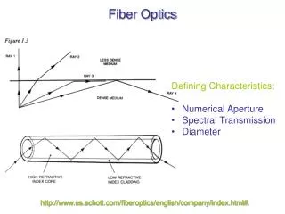
How Does an Optical Fiber Transmit Light? Suppose you want to shine a flashlight beam down a long, straight hallway. Just point the beam straight down the hallway -- light travels in straight lines, so it is no problem. What if the hallway has a bend in it? You could place a mirror at the bend to reflect the light beam around the corner. What if the hallway is very winding with multiple bends? You might line the walls with mirrors and angle the beam so that it bounces from side-to-side all along the hallway. This is exactly what happens in an optical fiber. Fiber Optics – light transmission
The light in a fiber-optic cable travels through the core (hallway) by constantly bouncing from the cladding (mirror-lined walls), a principle called total internal reflection. Because the cladding does not absorb any light from the core, the light wave can travel great distances. However, some of the light signal degrades within the fiber, mostly due to impurities in the glass. The extent that the signal degrades depends on the purity of the glass and the wavelength of the transmitted light (for example, 850 nm = 60 to 75 percent/km; 1,300 nm = 50 to 60 percent/km; 1,550 nm is greater than 50 percent/km). Some premium optical fibers show much less signal degradation -- less than 10 percent/km at 1,550 nm. Fiber Optics – light transmission
A Fiber-Optic Relay System To understand how optical fibers are used in communications systems, let's look at an example from a World War II movie or documentary where two naval ships in a fleet need to communicate with each other while maintaining radio silence or on stormy seas. One ship pulls up alongside the other. The captain of one ship sends a message to a sailor on deck. The sailor translates the message into Morse code (dots and dashes) and uses a signal light (floodlight with a venetian blind type shutter on it) to send the message to the other ship. A sailor on the deck of the other ship sees the Morse code message, decodes it into English and sends the message up to the captain. Fiber Optics – Relay System
Now, imagine doing this when the ships are on either side of the ocean separated by thousands of miles and you have a fiber-optic communication system in place between the two ships. Fiber-optic relay systems consist of the following: • Transmitter - Produces and encodes the light signals • Optical fiber - Conducts the light signals over a distance • Optical regenerator - May be necessary to boost the light signal (for long distances) • Optical receiver - Receives and decodes the light signals Fiber Optics – light transmission
Transmitter The transmitter is like the sailor on the deck of the sending ship. It receives and directs the optical device to turn the light "on" and "off" in the correct sequence, thereby generating a light signal. The transmitter is physically close to the optical fiber and may even have a lens to focus the light into the fiber. Lasers have more power than LEDs, but vary more with changes in temperature and are more expensive. The most common wavelengths of light signals are 850 nm, 1,300 nm, and 1,550 nm (infrared, non-visible portions of the spectrum). Fiber Optics – light transmission
Optical Regenerator As mentioned above, some signal loss occurs when the light is transmitted through the fiber, especially over long distances (more than a half mile, or about 1 km) such as with undersea cables. Therefore, one or more optical regenerators is spliced along the cable to boost the degraded light signals. An optical regenerator consists of optical fibers with a special coating (doping). The doped portion is "pumped" with a laser. When the degraded signal comes into the doped coating, the energy from the laser allows the doped molecules to become lasers themselves. The doped molecules then emit a new, stronger light signal with the same characteristics as the incoming weak light signal. Basically, the regenerator is a laser amplifier for the incoming signal. Fiber Optics – light transmission
Optical Receiver The optical receiver is like the sailor on the deck of the receiving ship. It takes the incoming digital light signals, decodes them and sends the electrical signal to the other user's computer, TV or telephone (receiving ship's captain). The receiver uses a photocell or photodiode to detect the light. Fiber Optics – light transmission
Advantages of Fiber Optics • Why are fiber-optic systems revolutionizing telecommunications? Compared to conventional metal wire (copper wire), optical fibers are: • Less expensive - Several miles of optical cable can be made cheaper than equivalent lengths of copper wire. This saves your provider (cable TV, Internet) and you money. • Thinner - Optical fibers can be drawn to smaller diameters than copper wire. • Higher carrying capacity - Because optical fibers are thinner than copper wires, more fibers can be bundled into a given-diameter cable than copper wires. This allows more phone lines to go over the same cable or more channels to come through the cable into your cable TV box. Advantages of Fiber Optics
Less signal degradation - The loss of signal in optical fiber is less than in copper wire. • Light signals - Unlike electrical signals in copper wires, light signals from one fiber do not interfere with those of other fibers in the same cable. This means clearer phone conversations or TV reception. • Low power - Because signals in optical fibers degrade less, lower-power transmitters can be used instead of the high-voltage electrical transmitters needed for copper wires. Again, this saves your provider and you money. • Digital signals - Optical fibers are ideally suited for carrying digital information, which is especially useful in computer networks. • Non-flammable - Because no electricity is passed through optical fibers, there is no fire hazard. Advantages of Fiber Optics
Lightweight - An optical cable weighs less than a comparable copper wire cable. Fiber-optic cables take up less space in the ground. • Flexible - Because fiber optics are so flexible and can transmit and receive light, they are used in many flexible digital cameras for the following purposes: • Medical imaging - in bronchoscopes, endoscopes, laparoscopes • Mechanical imaging - inspecting mechanical welds in pipes and engines (in airplanes, rockets, space shuttles, cars) • Plumbing - to inspect sewer lines Advantages of Fiber Optics
How Are Optical Fibers Made? Now that we know how fiber-optic systems work and why they are useful -- how do they make them? Optical fibers are made of extremely pure optical glass. We think of a glass window as transparent, but the thicker the glass gets, the less transparent it becomes due to impurities in the glass. However, the glass in an optical fiber has far fewer impurities than window-pane glass. One company's description of the quality of glass is as follows: If you were on top of an ocean that is miles of solid core optical fiber glass, you could see the bottom clearly. How Fiber Optics are made
Making optical fibers requires the following steps: • Making a preform glass cylinder • Drawing the fibers from the preform • Testing the fibers How Fiber Optics are made
Making the Preform Blank The glass for the preform is made by a process called modified chemical vapor deposition (MCVD). How Fiber Optics are made
In MCVD, oxygen is bubbled through solutions of silicon chloride (SiCl4), germanium chloride (GeCl4) and/or other chemicals. The precise mixture governs the various physical and optical properties (index of refraction, coefficient of expansion, melting point, etc.). The gas vapors are then conducted to the inside of a synthetic silica or quartz tube (cladding) in a special lathe. As the lathe turns, a torch is moved up and down the outside of the tube. The extreme heat from the torch causes two things to happen: How Fiber Optics are made
The silicon and germanium react with oxygen, forming silicon dioxide (SiO2) and germanium dioxide (GeO2). • The silicon dioxide and germanium dioxide deposit on the inside of the tube and fuse together to form glass. Lathe used in preparingthe preform blank How Fiber Optics are made
The lathe turns continuously to make an even coating and consistent blank. The purity of the glass is maintained by using corrosion-resistant plastic in the gas delivery system (valve blocks, pipes, seals) and by precisely controlling the flow and composition of the mixture. The process of making the preform blank is highly automated and takes several hours. After the preform blank cools, it is tested for quality control (index of refraction). How Fiber Optics are made
Drawing Fibers from the Preform Blank Once the preform blank has been tested, it gets loaded into a fiber drawing tower. The blank gets lowered into a graphite furnace (3,452 to 3,992 degrees Fahrenheit or 1,900 to 2,200 degrees Celsius) and the tip gets melted until a molten glob falls down by gravity. As it drops, it cools and forms a thread. How Fiber Optics are made
The operator threads the strand through a series of coating cups (buffer coatings) and ultraviolet light curing ovens onto a tractor-controlled spool. The tractor mechanism slowly pulls the fiber from the heated preform blank and is precisely controlled by using a laser micrometer to measure the diameter of the fiber and feed the information back to the tractor mechanism. Fibers are pulled from the blank at a rate of 33 to 66 ft/s (10 to 20 m/s) and the finished product is wound onto the spool. It is not uncommon for spools to contain more than 1.4 miles (2.2 km) of optical fiber. How Fiber Optics are made
Testing the Finished Optical Fiber • The finished optical fiber is tested for the following: • Tensile strength - Must withstand 100,000 lb/in2 or more • Refractive index profile - Determine numerical aperture as well as screen for optical defects • Fiber geometry - Core diameter, cladding dimensions and coating diameter are uniform • Attenuation - Determine the extent that light signals of various wavelengths degrade over distance How Fiber Optics are made