Download
1 / 6
60 likes | 105 Views
Matching Address. Validation board Ecal_Add value input. Area Hcal_Add (because sums2x2 in FE). Validation Board Hcal_Add value input. Matching: 1 Area Hcal_Add is corresponding with several Area Ecal_Add. 3 cases are possible according to detector structure geometry (topology).

E N D
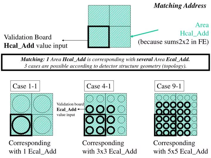
Matching Address Validation board Ecal_Add value input Area Hcal_Add (because sums2x2 in FE) Validation Board Hcal_Add value input Matching: 1 Area Hcal_Add is corresponding with several Area Ecal_Add. 3 cases are possible according to detector structure geometry (topology). Case 1-1 Case 4-1 Case 9-1 Corresponding with 1 Ecal_Add Corresponding with 3x3 Ecal_Add Corresponding with 5x5 Ecal_Add
Hcal address bus Validation Board Hcal_Add value input Hcal_Add bus (5bits) • Hcal_Add3 (5bits) • Hcal_Add2 (5bits) • Hcal_Add1 (5bits) • Hcal_Add0 (5bits) One validation board receive 4 Hcal_Add bus
Ecal address bus Validation Board Hcal_Add value input Area matching (case 4-1) with Hcal_Add • Ecal_Add7 (5bits) • Ecal_Add6 (5bits) • Ecal_Add5 (5bits) • Ecal_Add4 (5bits) • Ecal_Add3 (5bits) • Ecal_Add2 (5bits) • Ecal_Add1 (5bits) • Ecal_Add0 (5bits) Ecal_Add bus (5bits) One validation board receive 8 Ecal_Add bus Validation Board Ecal_Add value input
(Hcal+Ecal) logic in Validation board Max Hcal_Add3 matching_address 5 Sum ETRANS3 Hcal_Add2 mux 1 LUT 1 Kbits Hcal_Et3 Hcal_Add1 Hcal_Add0 Ecal_Add7 Clear 5 Max demux Sum ETRANS2 Ecal_Et7 8 Hcal_Et2 2bits Register Max Sum ETRANS1 routing_select (large matching) Hcal_Et1 ECAL Routing Max Sum ETRANS0 Hcal_Et0 8 box: One for each couple (Ecal_Et7, Ecal_Add7)(Ecal_Et6, Ecal_Add6)(Ecal_Et5, Ecal_Add5)(Ecal_Et4, Ecal_Add4) (Ecal_Et3, Ecal_Add3)(Ecal_Et2, Ecal_Add2)(Ecal_Et1, Ecal_Add1) (Ecal_Et0, Ecal_Add0) Each Register and LUT memory are programmable by ECS according to the detector topology.
LUT implementation 1K4 Memory block 5 + 1 Hcal_Add3 matching_address NC 5 Hcal_Add2 mux 5 NC 1 LUT 1 Kbits Hcal_Add1 Hcal_Add0 Ecal_Add7 Clear 5 demux Ecal_Et7 8 2bits Register routing_select (large matching) ECAL Routing Triple Voting In AX250 (Actel)
ECAL/HCAL logic implementation FPGA AX250 Input 168 Output 64 ECS (4)