Download
1 / 40
400 likes | 510 Views
MAE 242 Dynamics – Section I Dr. Kostas Sierros. Planar kinematics of a rigid body Chapter 16. Chapter objectives. To classify the various types of rigid-body planar motion To investigate rigid body translation and analyze it Study planar motion

E N D
MAE 242 Dynamics – Section I Dr. Kostas Sierros
Planar kinematics of a rigid body Chapter 16 Chapter objectives • To classify the various types of rigid-body planar motion • To investigate rigid body translation and analyze it • Study planar motion • Relative motion analysis using translating frame of reference • Find instantaneous center of zero velocity • Relative motion analysis using rotating frame of reference
Lecture 14 • Planar kinematics of a rigid body: • Absolute motion analysis, Relative motion analysis: Velocity, Instantaneous center of zero velocity, Relative motion analysis: Acceleration • -16.4-16.7
Material covered • Planar kinematics of a rigid body : • Absolute motion analysis • Relative motion analysis: Velocity • Instantaneous center of zero velocity • Relative motion analysis: Acceleration • …Next lecture…Review 2
Today’s Objectives • Students should be able to: • Determine the velocity and acceleration of a rigid body undergoinggeneral plane motionusing an absolute motion analysis (16.4) • Describe the velocity of a rigid body in terms of translation and rotation components (16.5) • Perform a relative-motion velocity analysis of a point on the body (16.5) • Locate the instantaneous center of zero velocity. • Use the instantaneous center to determine the velocity of any point on a rigid body in general plane motion (16.6) • Resolve the acceleration of a point on a body into components of translation and rotation (16.7) • Determine the acceleration of a point on a body by using a relative acceleration analysis (16.7)
Applications for absolute motion analysis (16.4) The position of the piston, x, can be defined as a function of the angular position of the crank, θ. By differentiating x with respect to time, the velocity of the piston can be related to the angular velocity, ω, of the crank.
Applications for absolute motion analysis (16.4) (continues) The rolling of a cylinder is an example of general plane motion. During this motion, the cylinder rotates clockwise while it translates to the right.
Absolute motion analysis (16.4) PROCEDURE FOR ANALYSIS Theabsolute motion analysis method(also called the parametric method) relates the position of a point, P, on a rigid body undergoing rectilinear motion to the angular position, q (parameter), of a line contained in the body. (Often this line is a link in a machine.) Once a relationship in the form of sP = f(q) is established, the velocity and acceleration of point P are obtained in terms of the angular velocity, w, and angular acceleration, a, of the rigid body by taking thefirst and second time derivativesof the position function. Usually thechain rulemust be used when taking the derivatives of the position coordinate equation.
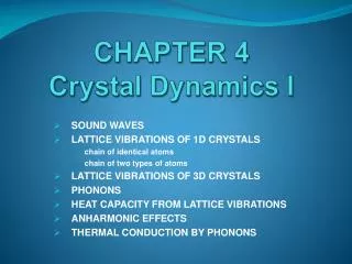
Problem 1 (16.4) Given:Two slider blocks are connected by a rod of length 2 m. Also, vA = 8 m/s and aA = 0. Find:Angular velocity, w, and angular acceleration, a, of the rod when q = 60°. Plan:Choose a fixed reference point and define the position of the slider A in terms of the parameter q. Notice from the position vector of A, positive angular position q is measured clockwise.
reference q A sA Problem 1 (16.4) continues Solution: By geometry, sA = 2 cos q By differentiating with respect to time, vA = -2 w sin q Using q = 60° and vA = 8 m/s and solving for w: w = 8/(-2 sin 60°) = - 4.62 rad/s (The negative sign means the rod rotates counterclockwise as point A goes to the right.) Differentiating vA and solving for a, aA = -2a sin q – 2w2 cos q = 0 a = - w2/tan q = -12.32 rad/s2
Applications for Relative motion analysis: Velocity (16.5) As the slider block A moves horizontally to the left withvA, it causes the link CB to rotate counterclockwise. ThusvBis directed tangent to its circular path.
= Disp. due to translation drB = drA + drB/A Disp. due to rotation Disp. due to translation and rotation Relative motion analysis (16.5) When a body is subjected to general plane motion, it undergoes a combination oftranslationandrotation. Point A is called thebase pointin this analysis. It generally has a known motion. The x’-y’ frame translates with the body, but does not rotate. The displacement of point B can be written:
= + Relative motion analysis: Velocity (16.5) The velocity at B is given as :(drB/dt) = (drA/dt) + (drB/A/dt)or vB=vA +vB/A Since the body is taken as rotating about A, vB/A =drB/A/dt =wxrB/A Herewwill only have akcomponent since the axis of rotation isperpendicularto the plane of translation.
Relative motion analysis: Velocity (16.5) continues vB =vA+wxrB/A When using the relative velocity equation, points A and B should generally be points on the body with a known motion. Often these points are pin connections in linkages. Here both points A and B have circular motion since the disk and link BC move in circular paths. The directions ofvAandvBare known since they are always tangent to the circular path of motion.
Relative motion analysis: Velocity (16.5) continues vB=vA+wxrB/A When a wheel rolls without slipping, point A is often selected to be at the point of contact with the ground. Since there is no slipping, point A has zero velocity. Furthermore, point B at the center of the wheel moves along a horizontal path. Thus,vBhas a known direction, e.g., parallel to the surface.
Relative motion analysis: Analysis procedure (16.5) Therelative velocity equationcan be applied using either a Cartesian vector analysis or by writing scalar x and y component equations directly. Scalar Analysis: 1.Establish the fixed x-y coordinate directions and draw akinematic diagramfor the body. Then establish the magnitude and direction of the relative velocity vectorvB/A. 2.Write the equationvB =vA+vB/Aand by using the kinematic diagram, underneath each term represent the vectors graphically by showing theirmagnitudes and directions. 3.Write the scalar equations from the x and y components of these graphical representations of the vectors. Solve for the unknowns.
Relative motion analysis: Analysis procedure (16.5) continues Vector Analysis: 1.Establish the fixed x-y coordinate directions and draw thekinematic diagramof the body, showing the vectorsvA,vB,rB/A andw. If the magnitudes are unknown, the sense of direction may be assumed. 2.Express the vectors inCartesian vector formand substitute intovB=vA +wxrB/A. Evaluate the cross product and equate respectiveiandjcomponents to obtain two scalar equations. 3. If the solution yields anegative answer, the sense of direction of the vector isopposite to that assumed.
Relative motion analysis: Velocity (16.5) Problem 2 Given:Block A is moving down at 2 m/s. Find:The velocity of B at the instant = 45. Plan:1.Establish the fixed x-y directions and draw a kinematic diagram. 2.Express each of the velocity vectors in terms of theiri, j, kcomponents and solvevB =vA + wx rB/A.
Relative motion analysis: Velocity (16.5) Problem 2 continues Solution: vB=vA +wABxrB/A vBi= -2j+ (wkx (0.2 sin 45i- 0.2 cos 45j)) vBi= -2j+ 0.2 w sin 45j + 0.2 w cos 45i Equating theiandjcomponents gives: vB = 0.2 w cos 45 0 = -2 + 0.2 w sin 45 Solving: w = 14.1 rad/s orwAB= 14.1 rad/sk vB = 2 m/s orvB= 2 m/si
Instantaneous center of zero velocity (16.6) Applications The instantaneous center (IC) of zero velocity for this bicycle wheel is at the point in contact with ground. The velocity direction at any point on the rim is perpendicular to the line connecting the point to the IC.
Instantaneous center of zero velocity (16.6) For any body undergoing planar motion, there always exists a point in the plane of motion at which thevelocity is instantaneously zero(if it were rigidly connected to the body). This point is called the instantaneous center of zero velocity, or IC. It may or may not lie on the body! If the location of this point can be determined, the velocity analysis can be simplified because the body appears to rotate about this point at that instant.
Location of center of zero velocity (16.6) To locate the IC, we can use the fact that thevelocity of a point on a body isalways perpendicularto therelative position vectorfrom the IC to the point. Several possibilities exist. First, consider the case when velocityvA of a point A on the body and the angular velocitywof the body are known. In this case, the IC is located along the line drawn perpendicular tovAat A, a distance rA/IC = vA/w from A. Note that the IC lies up and to the right of A sincevAmust cause a clockwise angular velocitywabout the IC.
Location of center of zero velocity (16.6) continues A second case is when thelines of action of two non-parallel velocities,vAandvB,are known. First, construct line segments from A and B perpendicular tovAandvB. The point of intersection of these two line segments locates the IC of the body.
Location of center of zero velocity (16.6) continues A third case is when themagnitude and direction of two parallel velocitiesat A and B are known. Here the location of the IC is determined by proportional triangles. As a special case, note that if the body is translating only (vA=vB), then the IC would be located at infinity. Then w equals zero, as expected.
Velocity analysis (16.6) The velocity of any point on a body undergoing general plane motion can be determined easily once the instantaneous center of zero velocity of the body is located. Since thebody seems to rotate about the IC at any instant, as shown in this kinematic diagram, the magnitude of velocity of any arbitrary point isv = w r,where r is the radial distance from the IC to the point. The velocity’s line of action is perpendicular to its associated radial line. Note thevelocity has a sense of directionwhich tends to move the point in a manner consistent with the angular rotation direction.
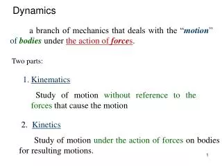
Given:The disk rolls without slipping between two moving plates. vB = 2v vA = v Problem 3 (16.6) Find: The angular velocity of the disk. Plan:This is an example of the third case discussed in the lecture notes.Locate the IC of the disk using geometry and trigonometry. Then calculate the angular velocity.
v A x IC w O r B 2v Problem 3 continues (16.6) Solution: Using similar triangles: x/v = (2r-x)/(2v) or x = (2/3)r Therefore w = v/x = 1.5(v/r)
Relative motion analysis: Acceleration (16.7) Applications In the mechanism for a window, link AC rotates about a fixed axis through C, while point B slides in a straight track. The components of acceleration of these points can be inferred since their motions are known. To prevent damage to the window, the accelerations of the links must be limited.
Relative motion analysis: Acceleration (16.7) = + dv dv dv / B A B A dt dt dt These are absolute accelerations of points A and B. They are measured from a set of fixed x,y axes. This term is the acceleration of B with respect to A. It will developtangentialandnormal components. The equation relating the accelerations of two points on the body is determined by differentiating the velocity equation with respect to time. The result isaB= aA+(aB/A)t+ (aB/A)n
Relative motion analysis: Acceleration (16.7) continues Graphically: aB = aA+ (aB/A)t + (aB/A)n = + The relative tangential acceleration component(aB/A)tis ( xrB/A) andperpendicular torB/A. The relative normal acceleration component(aB/A)n is (-2rB/A) andthe direction is always from B towards A.
Relative motion analysis: Acceleration (16.7) continues Since the relative acceleration components can be expressed as (aB/A)t = rB/Aand (aB/A)n = - 2rB/A the relative acceleration equation becomes aB=aA+ rB/A - 2rB/A Note that thelast termin the relative acceleration equation isnot a cross product. It is the product of a scalar (square of the magnitude of angular velocity, w2) and the relative position vector, rB/A.
Application of relative acceleration equation In applying the relative acceleration equation, the two points used in the analysis (A and B) should generally be selected as points which have aknown motion, such aspin connectionswith other bodies. In this mechanism, point B is known to travel along acircular path, soaBcan be expressed in terms of its normal and tangential components. Note that point B on link BC will have thesame accelerationas point B on link AB. Point C, connecting link BC and the piston, moves along astraight-linepath.Hence,aCis directed horizontally.
Procedure of analysis (16.7) 1. Establish a fixed coordinate system. 2.Draw the kinematic diagram of the body. 3.Indicate on itaA,aB,,, andrB/A.If the points A and B move along curved paths, then their accelerations should be indicated in terms of their tangential and normalcomponents, i.e.,aA= (aA)t+ (aA)nandaB = (aB)t+(aB)n. 4.Apply the relative acceleration equation: aB=aA+rB/A- 2rB/A 5.If the solution yields a negative answer for an unknown magnitude, it indicates the sense of direction of the vector is opposite to that shown on the diagram.
Bodies in contact (16.7) Consider two bodies in contact with one anotherwithout slipping,where the points in contact move alongdifferent paths. In this case, thetangential componentsof acceleration will be thesame, i. e., (aA)t= (aA’)t (which implies aBrB = aCrC ). The normal componentsof acceleration willnot be the same. (aA)n (aA’)n soaAaA’
Rolling motion (16.7) Another common type of problem encountered in dynamics involvesrolling motion without slip; e.g., a ball or disk rolling along a flat surface without slipping. This problem can be analyzed using relative velocity and acceleration equations. As the cylinder rolls, point G (center) moves along astraight line, while point A, on the rim of the cylinder, moves along acurved pathcalled acycloid. Ifwandaare known, the relative velocity and acceleration equations can be applied to these points, at the instant A is incontactwith the ground.
Rolling motion (16.7) continues • Velocity: Since no slip occurs, vA = 0 when A is in contact with ground. From the kinematic diagram: vG = vA + w x rG/A vG i = 0 + (-w k) x (r j) vG = wr or vG = wr i • Acceleration: Since G moves along a straight-line path, aG is horizontal. Just before A touches ground, its velocity is directed downward, and just after contact, its velocity is directed upward. Thus, point A accelerates upward as it leaves the ground. aG = aA + a x rG/A – w2rG/A => aGi = aAj + (-ak) x (r j) – w2(r j) Evaluating and equating i and j components: aG = ar and aA = w2r or aG = ar i and aA = w2r j
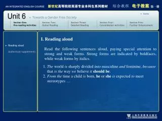
Problem 4 (16.7) Given:The ball rolls without slipping. Find:The accelerations of points A and B at this instant. Plan:Follow the solution procedure. Solution:Since the ball is rolling without slip,aOis directed to the left with a magnitude of: aO= r= (4 rad/s2)(0.5 ft)=2 ft/s2
Problem 4 (16.7) continues Now, apply the relative acceleration equation between points O and B. aB = aO + a x rB/O – w2rB/O aB = -2i + (4k) x (0.5i) – (6)2(0.5i) = (-20i + 2j) ft/s2 Now do the same for point A. aA = aO + a x rA/O – w2rA/O aA = -2i + (4k) x (0.5i) – (6)2(0.5j) = (-4i – 18j) ft/s2
TASKS Next Tuesday REVIEW 2 Team design project: 13-1D (page 161) Ramp catapult Finalize design of catapulting mechanism Next Thursday Midterm Exam 2 Next Friday is FINAL DAY to DROP the course