Download
1 / 20
200 likes | 333 Views
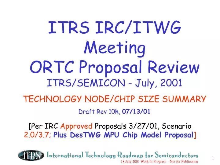
[Per IRC Approved Proposals 3/27/01, Scenario 2.0/3.7; Plus DesTWG MPU Chip Model Proposal ]. ITRS IRC/ITWG Meeting ORTC Proposal Review ITRS/SEMICON - July, 2001 TECHNOLOGY NODE/CHIP SIZE SUMMARY Draft Rev 10 h , 07/13/01. S=0.7 [0.5x per 2 nodes]. Pitch. Gate.

E N D
[Per IRC Approved Proposals 3/27/01, Scenario 2.0/3.7; Plus DesTWG MPU Chip Model Proposal] ITRS IRC/ITWG Meeting ORTC Proposal Review ITRS/SEMICON - July, 2001 TECHNOLOGY NODE/CHIP SIZE SUMMARY Draft Rev 10h, 07/13/01
S=0.7 [0.5x per 2 nodes] Pitch Gate MOS Transistor Scaling(1974 to present)
0.7x 0.7x 250 -> 180 -> 130 -> 90 -> 65 -> 45 -> 32 -> 22 -> 16 0.5x N N+1 N+2 Scaling Calculator
1994 NTRS - .7x/3yrs Log Half-Pitch Actual - .7x/2yrs 0.7x 0.7x Linear Time 250 -> 180 -> 130 -> 90 -> 65 -> 45 -> 32 -> 22 -> 16 0.5x Node Cycle Time (T yrs): *CARR(T) = [(0.5^.5)^(1/T yrs)] - 1 CARR(3 yrs) = -10.9% CARR(2 yrs) = -15.9% N N+1 N+2 * CARR(T) = Compound Annual Reduction Rate (@ cycle time period, T) Scaling Calculator + Node Cycle Time:
ITRS Approved Scenario Proposal (4/26/01 Grenoble) Scenarios 2.0(DRAM), 3.7(MPU), 3.7 (ASIC/Low Power) the DRAM Half-pitch (HP) should remain on a 3-year-cycle trend after 130nm/2001 (Sc 2.0). • the MPU/ASIC HP* may be on a 2-year-cycle trend until 90nm/2004, and then remain equal to DRAM HP Sc 2.0 on a 3-year cycle (Sc 3.7). • the MPU (HP) Printed (PrGL) and Physical (PhGL) Gate Length will be on 2-year-cycle trends until 45nm and 32nm, respectively, at year 2005, and then parallel to the DRAM/MPU HP trends on a 3-year cycle (Sc 3.7). • the ASIC/Low Power Pr/PhGL is delayed 2 years behind MPU Pr/PhGL per Grenoble 4/26,27 ITRS meetings; *ASIC HP equal to MPU HP
Scenario 2.0/DRAM 3.7/MPU (2-yr cycle M/A HP & G.L. <2005; 3yr >2005) ITRS Roadmap Acceleration Continues... 95 97 99 01 04 07 10 13 16 500 500 2-Year Node Cycle 1995-2001 Sc 3.7 MPU/ASIC Half-Pitch (1-year Lag Thru 2002, then equal to DRAM after 2004) 350 350 250 250 (DRAM Half Pitch) Technology Node 180 180 1998/1999 DRAM Half-Pitch MPU/ASIC 130 130 Feature Size (nm) 2000 Update, Sc 2.0 Gate Length 100 100 XX Technology Node - DRAM Half-Pitch (nm) Minimum 90 DRAM Sc 2.0 = 3-yr cycle after 2001 70 XX 70 Feature Size 65 50 XX 50 45 35 MPU/ASIC Gate XX In Resist “ ” 1999 ITRS 35 32 25 XX 25 22 16 95 97 99 01 04 07 10 13 16 ~.7x per 11 Year of Production technology 2001 Renewal Period “Most Aggressive” Sc 3.7 = 2-yr<’05; 3-yr >’05: MPU Printed (PrGL) & Physical (PhGL) Gate Length cycle; (ASIC/Lo Power Pr/PhGL 2-year delay from MPU Pr/PhGL) node (.5x 8.0 per 2 nodes)
107 28 MPU/ ASIC 2001 Renewal ORTC DRAM and MPU Technology Node Tables 1a,b [ITRS Typical Table Header Format ]
MPU/ ASIC 107 28 *ASIC GL = 2-year delay from MPU GL 130 107 90 75 65 53 45 32 22 16 90 75 65 53 45 37 32 22 16 11 MPU/ ASIC * * 2001 Renewal ORTC ASIC Technology Node Tables 1aa,ba [ITRS ASIC/Low Power Chapter Table Header Format ]
Samsung @ ISSCC/Feb2001: 4Gb DRAM, 645mm2, [0.15u2 ave cell area] (ITRS: 0.13u2/2001) 2000 Update [Sc. 2.0/3.7] [Approved for use in 2001 Renewal w/MPU Sc. 3.7] DRAM Chip size - 2000 ITRS ORTC Update Proposal [Sc. 2.0]
800mm2 Litho Field Size 572mm2 Litho Field Size 286mm2 2 per Field Size 310mm2 340mm2 170mm2 Sc 3.7: Flat Thru 2004 85mm2 42mm2 MPU Chip size - 2000 ITRS ORTC Update Proposal [ Sc. 2.0 vs 3.7 vsDesign TWG 3.7 ] HP MPU 310mm2 1999 Typical .18u HP MPU: 2MB (113Mt x 1.18u2/t = 135mm2) + 25Mt Logic x 5.19u2/t = 130mm2 + 45mm2 OH= 310mm2 = Total 138Mt x ave 2.25u2/t = 310mm2 CP MPU 140mm2 1999 Typical .18u CP MPU: 512KB (28Mt x 1.18u2/t = 34mm2) + 20Mt Logic x 5.19u2/t = 104mm2 + 2mm2 OH= 106mm2 = Total 48Mt x ave 2.92u2/t = 140mm2 Design TWG MPU Transistors/Chip Proposal: ~2x/Node = 2x/2yrs from 1999-2001; then 2x/3yrs from 2001-2016
SRAM A-Factors for Simple 6T SRAM Cell using Microprocessor Logic CMOS Process Technology ‘94-’00 Historical A-factor Reduction Rate Ave = 0.967x = -3.3% CAGR [1999 ITRS Target: -7% CAGR**] Average A-Factor = 161.67 ‘98-’00 Historical A-factor Reduction Rate Ave = 0.913x = -8.7% CAGR Cell Size (u2) 2.43 u2 2.48 u2 5.59 u2 10.3 u2 20.5 u2 15.8 u2 ** 1.2x/4yrs “affordable” MPU chip size growth; @ 2x/2yrs Transistors/chip Function Growth; @ 0.5x/3yrs Technology Node (f) Reduction
Design TWG MPU Chip Size Model Proposal 137f2 x1.6 ITRS Chip Size Model Proposal: Sc 2.0/DRAM [no change]; Sc 3.7/MPU Proposal: Li = MPU 4t Gate; Ai = ASIC 4t Gate; Si = 6t SRAM cell; St = SRAM transistor L 97f2 x1.6 S L Li L Li Li L 320f2 x2 320f2 x2 S Li Ai Ai 320f2 x2 Si Li Si St 137f2 x1.6 Ai S St Li Si St Ai S Si St Li Ai 23f2 x1.6 St Si Ai Li St Si Ai 320f2 x2 Li St Si Ai St Si 97f2 x1.6 Ai Si St 13f2 x1.6 = ASIC Gate (4t) , eSRAM (6t) (Design TWG) Chip Function Density Trend Chart - ITRS Proposal 3.7
Design TWG MPU Frequency Proposal: ~2x/3yrs from 2001-2010; then 2x/5yrs from 2010-2016 Sc 3.7 - w/Innovation* : 2x/2yrs Non-Gate-Length Performance Innovation* 1999 ITRS 9.6Ghz/11nm 25Ghz/4.2nm 4.8Ghz/22nm 2.4Ghz/45nm 1.2Ghz/90nm 3.4Ghz/32nm .6 Ghz/180nm 1.7Ghz/65nm 2023 2011 .3 Ghz/350nm 2001 2005 Sc 3.7 w/o Innov.*:1999- 2005 Freq = 2x/4yrs ; GL = .71x/2yr 2005- 2016 Freq = 2x/6yrs ; GL = .71x/3yr Historical: Freq = 2x/2yrs ; GL = .71x/yr 1995 1999 1997 2003 2008 2014 Log Frequency MPU Max Chip Frequency - ITRS GL Proposal Sc 3.7
Backup: • DRAM Chip Size Model (Sc. 2.0) • Including Corrections to 2003/6x Cell Factor, and Kawamura Bit Growth model • MPU Chip Size Model (Sc. 3.7) • Including Updated SRAM Density Model, and MPU flat chip size to 2004 • FI TWG Fab Ramp, Wafer Generation Model Proposals • Including Alpha, Beta Tool Timing, and wafer ramp for first fabs • ORTC Other Table Index/Owners • Roadmap Definitions/Guidelines
28 28 14 107 New Design TWG MPU Model
20Kwspm 5000 4.5Kwspw (19.5Kwspm) 4500 4000 3500 3000 2500 Beta - Tools, P.O. for Production Capacity 2000 1500 1000 500 0 1 5 9 13 17 21 25 29 33 37 41 45 49 12 months 12 months Weeks From Ramp Start 6 months Alpha - Tools 12 months 100 wafers/week = 10K-25K Die/week (@170mm2 die size) Time to Reach 100% Capacity Proposed ITRS Fab Ramp Model • High volume = 4500 wafer starts per week or 20k wspm • Ramp from 100 to 4500 wafers per week takes 6 to 12 months • 6 month ramps are used when fewer process changes are introduced or higher risk is acceptable • 12 month ramps are used when more process changes are introduced or lower risk is desired • This is for the leading edge IC maker’s first high volume factory for a major technology node [ex: 180nm to 130nm transition] • Time to ramp minor technology shrinks [ex: 130nm to 115nm] is 6 to 9 months
IBM Driven Intel Driven Consortia Driven (I300I/J300/etc) Consortia Driven (??I450I/J450??) Alan Allan IRC Slide FI TWG Wafer Generation Timing Proposal: Make 450mm Wafer Intercept at 2013 • Background • Wafer size changes are driven by productivity curve to continue Moore’s law. Need to move to 450mm may be accelerate or slow based on economic needs. • Historically, wafer size changes are done every 9 years • Logic for 2013 • 1999 roadmap placed 450mm change at 2014. Data to predict the intercept is no better now so use the same approximate timing -> use 2013 node since 2014 node does not exist.
Other ORTC Table TWG Line Items - Table 2a,b Litho Field Size Litho Wafer Size FEP, FI - Table 3a,b # of Chip I/O’s Test, Design # of Package Pins/Balls Test, A&P - Table 4a,b Chip Pad Pitch A&P Cost-Per-Pin A&P Chip Frequency Design Chip-to-Board Frequency A&P Max # Wire Levels Interconnect - Table 5a,b Electrical Defects Def. Reduct. - Table 6a,b P.Supply Volt. PIDs Max. Power Design, PIDs - Table 7a,b Affordable Cost Economic (AA actg) Test Cost Test
ITRS Table Definitions/Guidelines - 2001Proposal Rev0, 10/02/00 [As Presented in IRC/Taiwan 12/06/01] • Technology Requirements Perspective - Near-Term Years : First Yr. Ref.+ 6 yrs F’cast (ex. 2001 through 2007), annually - Long-Term Years : Following 9 years (ex.: 2010, 2013, and 2016), every 3 years • Technology Node : - General indices of technology development. - Approximately 70% of the preceding node, 50% of 2 preceding nodes. - Each step represents the creation of significant technology progress - Example: DRAM half pitches: 130, 90, 65, 45, 32, 22, 16 nm -Smallest 1/2 pitch among DRAM, ASIC, MPU, etc • Year of Production: - The volume = 10K units (devices)/month. ASICs manufactured by same process technology are granted as same devices - Beginning of manufacturing by a company and another company starts production within 3 months • Technology Requirements Color: - : Manufacturable Solutions are NOT known - : Manufacturable Solutions are known - : Manufacturable Solutions exist, and they are being optimized - Red cannot exist in the next three years (2002, 2003, 2004) ** - Yellow cannot exist the next year (2002) ** White Red Yellow ** Exception [By Review/Approval of IRC]: Solution NOT known, but does not prevent Production manufacturing