Download
1 / 30
530 likes | 1k Views
Lighting and Wiring Service. Chapter 33. Objectives. Diagnose problems in lighting and wiring systems Adjust headlamp aim Make repairs to automotive wiring, lamps and bulbs, and protection devices. Analyzing Electrical Problems. Diagnose problem cause Verify the complaint

E N D
Lighting and Wiring Service Chapter 33
Objectives • Diagnose problems in lighting and wiring systems • Adjust headlamp aim • Make repairs to automotive wiring, lamps and bulbs, and protection devices
Analyzing Electrical Problems • Diagnose problem cause • Verify the complaint • Check for related symptoms • Check wiring diagram for common problems • Problem types • Open circuit: break in continuity • Short circuit: unwanted current path • Grounded circuit: short circuit to ground • Excessive resistance: reduces current flow • Corroded connector is a common cause
Wiring Service • Wiring diagrams: road maps to electrical circuits • Wires are numbered or colored • First color is insulation; second is stripe • Numbers refer to wire gauge or locations • Letters preceding the number • G: grounds • S: splices • C: connectors • SAE wiring diagrams • Arranged so upper right is power feed • Lower right is ground
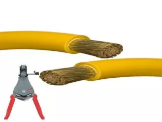
Crimp Terminals • Install terminal on wire • Strip about ¼ inch of insulation from end of wire • Insert wire end into terminal and crimp • Poor crimp creates excessive resistance • W-crimp crimps longitudinally • Terminal block keeps wires organized • Depress locking tang to remove terminals • Crimp connectors splice wires together • Insert both ends into connector and then crimp • Wires should be side by side
Selecting Replacement Wire • Replacement wire and cable • Comes wound in spools • Use wire adequate for load • Replacement wire should be at least as big as original • Wire that is too small or too long causes excessive resistance • Doubling the length doubles the resistance
Adding Electrical Accessories • Aftermarket accessories • Usually require separate fused circuit • Fuse holders • Original equipment accessories take power from a fuse on the fuse panel • Fuse holder can be connected to existing power source • Tap splice connectors are used in electrical circuits only, not in electronic circuits
Soldering • Preferred for electronic circuits • Small amount of current runs through • Does not suffer increased resistance due to oxidation • Soldering iron is used for wiring connections • Propane, acetylene, Mapp gas torch are used for radiators or larger cable terminal connections • Stainless steel is not solderable • Flux cleans metal so solder will stick
Soldering (cont'd.) • Cold solder connection • Solder melts but wire does not bond to it • Heat-shrink tubing • Insulates a solder joint and makes it airtight • Connection can also be insulated with vinyl tape • Adhesive-lined tubing • Recommended to prevent corrosion
Broken or Damaged Ground Straps • Engine and body: isolated from frame with rubber mounts • Ground straps between engine and chassis provide path back to battery through frame • Broken ground strap may cause: • Burned transmission bushing and drive shaft yolk • Burned emergency brake cables • Burned carburetor return spring • Flickering headlights • Burned front-wheel bearings or CV joints
Circuit Testing and Service • Fuse failure • Replaced fuse does not fix the problem that caused the overload • Fix the problem before restoring circuit protection • Corrosion at fuse end can cause failure • Fuses are rated according to current capacity • Not voltage • Fuses have 10% overload factor • Guards against minor power surges
Finding Grounds • Locating the cause of a grounded wire • Install a circuit breaker temporarily • Install a test light in series with the circuit breaker • Disconnect individual circuits • Circuit disconnected when light goes out is at fault • Compass or Gauss meter • Locates ground location • Ohmmeter • Detects grounded circuit
Fuse Testing and Service • Checking fuses • Visual check, ohmmeter, and test light • Removing fuses • Blade-type: removed by hand or with pliers • Test light does not glow on either circuit side • Circuit is shut off • Circuit is broken • Tester does not have good ground connection • Be sure replacement fuse has correct rating
Fuse Link Service • Fuse link • Length of wire covered with insulation that is thicker than normal insulation • Can contain melted metal if a wire fails • Insulation bubbles if fuse link melts • Cut out damaged part of wire • Splice new fuse link • Use a fuse link of the correct size
Headlamp Service • Headlight: light beam from a headlamp • Replacing a headlamp • Halogen and conventional sealed beams will fit into same brackets • Round type I and type II lamps do not interchange • Use dielectric grease when installing headlight • Halogen lamp replacement • Sealed-beam halogen lamps: replaced as a unit
Headlamp Service (cont’d.) • Composite halogen lamp insert replacement • Removing a halogen replaceable lamp insert in a composite light assembly • Touch it only on its plastic base • HID lamp service • High-intensity discharge (HID) lamps • Expensive but reliable • Two to three times less likely to fail
Headlight Aiming • Properly aimed low-beams: face down and right • Before adjusting headlights check that the: • Vehicle is carrying its typical load • Trunk is carrying typical amount of material • Gas tank is half-full • Driver’s weight is accounted for • Headlight-mounted aimers • Use bubble levels to calibrate vertical alignment • Horizontal alignment compares headlights to see they are parallel
Headlight Aiming (cont'd.) • Electronic optical aimers • Laser technology is used to square and align • Locating the optical center of the headlight • Electronic optical headlight aimer slides on track • Aimer alignment to headlight • Align the aimer to the headlight • Lamp audit and aim • Follow arrow indicator • More precise aiming • Use “Aim Lamp” button
Tail Lamp and Park Light Service • Lamps may be accessed from inside the trunk • Others require removal of light lens • Excessive voltage • Shortens the life of a light bulb • Voltage higher by five percent reduces bulb life by half • Malfunctioning charging system is the only cause of excessive voltage
LED Service • Light-emitting diodes (LEDs) • Sometimes used for headlights, brake lights, turn signals, and taillights • Also used in side rear view mirror turn signal indicators and center high-mount stop lamps • Not serviceable; they are replaced • Use less current than filament light bulbs
Stoplight Switch Service • Bypass stoplight switch with jumper wire to test • Stoplights should light when wires are connected • Use a test light to see if there is power at one end • If lights come on when wires connected, but not when brakes are applied, replace the switch • If lights stoplights operate without key, remove the fuse before removing switch • If new switch adjustable, adjust it so it is open when the pedal is released
Back-Up Lights • Back-up light circuit components • Fuse • Shift lever or transmission mounted switch • Sometimes adjustable • Wiring • Lights • Back-up lights could come on in a gear range other than reverse • Check the service information for adjustment procedures
Turn Signal Switch • Defective switch • May not cancel signal following sharp turn • Brake light problems may be caused by defective signal switch • Multifunction switch removal • Most newer passenger vehicles use a multifunction switch • Includes turn signal switch • Can often be removed without removing steering wheel
Signal Flasher/Relay • Electronic signal flashers • Flash faster than normal when bulb has failed • Mechanical flashers flash slower • Turn on hazards and walk around the car to check filaments of signal bulbs and break lights
Locating a Signal Flasher • Several flasher locations • In the fuse panel • Under the dash in a wiring loom • In glove box • Under the hood • Location flashers • Most are located under dashboard on driver’s side • Working: can be located by clicking sound • Not working: use service information
Instrument Panel Bulbs and Windshield Washer Service • Small bulbs resembling photo flash bulbs • Printed circuit dash boards • Housed in plastic connector • Turn ¼ turn counterclockwise to remove • Primary reason for windshield washer problems • Restriction in washer nozzle • Pull one of the hoses off a nozzle and operate washer • Fluid is pumped from end of hose: clean nozzle • No fluid pumped: check fuse • Problem is with pump: replace it
Horn Service and Gauge Testing • Horn does not work: check fuse • Horn can adjusted by changing the spring tension on the armature • When a gauge does not operate: check its fuse • Fuse in tact, but no power: check wiring diagram • Work toward battery checking voltage • Sending unit tests • Use an ohmmeter to check resistance between the terminal of the sending unit and ground