Download
1 / 38
380 likes | 521 Views
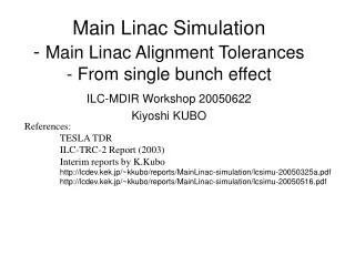
MAIN LINAC DDS DESIGN. Vasim Khan 06.11.09. Bohr seminar series, HEP group, The University of Manchester. Outlook. CLIC scheme Two Beam Acceleration Optimised parameters What is wakefield Main Linac Design constraints Present structure Our DDS design Comparison Forthcoming.

E N D
MAIN LINAC DDS DESIGN Vasim Khan 06.11.09 Bohr seminar series, HEP group, The University of Manchester
Outlook • CLIC scheme • Two Beam Acceleration • Optimised parameters • What is wakefield • Main Linac • Design constraints • Present structure • Our DDS design • Comparison • Forthcoming V. Khan Bohr seminar series, HEP group, The University of Manchester 06.11.09 1/34
e- e+ collider • C. M. Energy : 3 TeV • Normal conducting technology • Frequency : 12 GHz • Acc. Gradient : 100 MV/m • Luminosity : ~ 1034 cm-2 s-1 • Novel technique : Two beam acceleration • Overall site length 48 km........(compact ?) CLIC scheme V. Khan Bohr seminar series, HEP group, The University of Manchester 06.11.09 2/34
CLIC parameters* * H. Braun, et al. , Updated CLIC Parameters, CLIC-Note 764, 2008. V. Khan Bohr seminar series, HEP group, The University of Manchester 06.11.09 3/34
CLIC complete layout SECTOR/LINAC: 24 PETS/SCTOR: 1491 No. of acc. Str./PETS: 2 Main Linac Ref: H. Braun, et al. , Updated CLIC Parameters, CLIC-Note 764, 2008. V. Khan Bohr seminar series, HEP group, The University of Manchester 06.11.09 4/34
Two Beam Acceleration • 140,000 main linac structures. • It is difficult to supply power using conventional RF source i.e. Klystron......it will require 10,000’s of such klystrons. • A low energy high current beam (drive beam) running parallel to the main beam. • Drive beam interacts with the impedance of the Power Extraction and Transfer Structures. • Drive beam is thus decelerated. • The decelerated energy is used to accelerate main beam. V. Khan Bohr seminar series, HEP group, The University of Manchester 06.11.09 5/34
Why ? • 1) Linacs ? • 2) Normal conducting ? • 3) X-band frequency of 12 GHz ? Synchrotron radiation [1] Energy loss per revolution [1] [1] S.Y. Lee, Accelerator Physics. * Assume a circular CLIC collider (very impractical) V. Khan Bohr seminar series, HEP group, The University of Manchester 06.11.09 6/34
Is there any energy loss in linear acceleration ? In Linac we consider the power radiated to the power supplied by an external source [1] [1] S.Y. Lee, Accelerator Physics. *Assume if CLIC was proposed to accelerate with accelerating gradient of ~2.75 GeV/m (an impossibly large gradient) V. Khan Bohr seminar series, HEP group, The University of Manchester 06.11.09 7/34
Normal conducting ? Frequency scaling of rf parameters • Need high gradient for a feasible site length • High gradient cavities will have high surface fields • Super conducting (SC) cavities can be operated up to ~ 40 MV/m • High gradient in SC cavities will quench the superconductivity. • Possible option is Normal Conducting (NC) cavities. V. Khan Bohr seminar series, HEP group, The University of Manchester 06.11.09 8/34
X-band (8-12 GHz)? • Initial proposal was 150 MV/m @ 30 GHz • Operation with these parameters will suffer major breakdown issues • The optimisation procedure has resulted in 100 MV/m gradient with 12 & 14 GHz frequency option. • 12 GHz frequency was chosen to utilise more than two decades of R & D in the NLC/GLC project which was also proposed at 12 GHz. V. Khan Bohr seminar series, HEP group, The University of Manchester 06.11.09 9/34
What is wakefield ? V. Khan Bohr seminar series, HEP group, The University of Manchester 06.11.09 10/34
What is wakefield ? • Fields excited by the ultra relativistic (v~c) particles • Short range wake :tail of the bunch experiences field excited by the head of the bunch • Long range wake : trailing bunches experience fields excited by the leading bunches • Transverse wake : emittance dilution luminosity dilution • Longitudinal : energy spread ε= Emittance σ= Beam size β= Beta function L=Luminosity V. Khan Bohr seminar series, HEP group, The University of Manchester 06.11.09 10/34
Main Linac ~25 cm V. Khan Bohr seminar series, HEP group, The University of Manchester 06.11.09 11/34
Fundamental concepts • Synchronous mode : Most dominating mode in an accelerating cell, its phase vel. is in synchronous with speed of light • Bandwidth : Difference between the synchronous frequencies of the end cells (lowest dipole ) • Large BW : 3.3 GHz • Small BW : 1 GHz • Moderate BW : 2.3 GHz • Heavy Damping : Q ~10[1] • Moderate Damping : Q ~500-1000[2] Syn. mode Light line Ref: [1]: A. Grudiev and W. Wuenschs, LINAC08 . [2]: R. Jones, et al. , PRSTAB 9, 102001, (2006). V. Khan Bohr seminar series, HEP group, The University of Manchester 06.11.09 12/34
Constraints • Beam dynamics constraints [1],[2] • For a given structure, no. of particles per bunch N is decided by the <a>/λ and Δa/<a> • Maximum allowed wake on the first trailing bunch • Rest of the bunches should see a wake less than this wake(i.e. No recoherence). RF breakdown constraint [1],[2] 1) 2) Pulsed surface heating 3) Cost factor Ref: [1]: A. Grudiev and W. Wuensch, Design of an x-band accelerating structure for the CLIC main linacs, LINAC08 . [2]: H. Braun, et al. , Updated CLIC Parameters, CLIC-Note 764, 2008. V. Khan Bohr seminar series, HEP group, The University of Manchester 06.11.09 13/34
Accelerating cells : Several designs 4.5 mm V. Khan Bohr seminar series, HEP group, The University of Manchester 06.11.09 14/34
Wakefield suppression in CLIC main linacs The present main accelerating structure (WDS) for the CLIC relies on linear tapering of cell parameters and heavy damping with a Q of ~10. The wake-field suppression in this case entails locating the dielectric damping materials in relatively close proximity to the location of the accelerating cells. To minimise the breakdown probability and reduce the pulse surface heating, we are looking into an alternative scheme for the main accelerating structures: • Detuning the first dipole band by forcing the cell parameters to have Gaussian spread in the frequencies • Considering the moderate damping Q~500 V. Khan Bohr seminar series, HEP group, The University of Manchester 06.11.09 15/34
CLIC_G: Present baseline waveguide damped design Ref: A. Grudiev, W. Wuensch, Design of an x-band accelerating structure for the CLIC main linacs, LINAC08 Ref: R. Jones, PRSTAB 12, 104801, (2009). V. Khan Bohr seminar series, HEP group, The University of Manchester 06.11.09 16/34
Damped and detuned design • Detuning: A smooth variation in the iris radii spreads the dipole frequencies. This spread does not allow wake to add in phase • Error function distribution to the iris radii varion results in a rapid decay of wakefield. • Due to limited number of cells in a structure (trunated Gaussian) wakefield recoheres. • Damping: The recoherence of the wakefield is suppressed by means of a damping waveguide like structure (manifold). • Interleaving neighbouring structure frequencies help enhance the wake suppression V. Khan Bohr seminar series, HEP group, The University of Manchester 06.11.09 17/34
Acceleration cells Beam tube Manifold HOM coupler High power rf coupler NLC/GLC DDS design Ref: R. Jones, et al. , PRSTAB 9, 102001, (2006). V. Khan Bohr seminar series, HEP group, The University of Manchester 06.11.09 18/34
Advantages • Moderate damping scheme: Breakdown probability is reduced • Pulse temperature rise is reduced • Manifolds can be used for beam position monitoring and remote measurements of cell alignments*. * Ref: R. Jones, et al. , SLAC-PUB 7388, 1996. R. Jones, et al. , SLAC-PUB 7539, 1997 Cell offsets of DDS1 obtained by coordinate measurement machine (CMM), indicated by red connected dots and, inferred from the energy radiated from the HOM ports (Pmin), indicated by a black dashed line. Disadvantages • Need bigger bandwidth for adequate detunig and hence more input power to achieve desired accelerating gradient V. Khan Bohr seminar series, HEP group, The University of Manchester 06.11.09 19/34
Key parameters for designing an accelerating structure @ 12 GHz & 100 MV/m • Iris radii of the end cells • Iris thickness • <a>/λ • Group velocity • No. of cells per structure • Bunch spacing • Bunch charge • No. of bunches in a train => pulse length V. Khan Bohr seminar series, HEP group, The University of Manchester 06.11.09 20/34
Large bandwidth structure Error function distribution V. Khan Bohr seminar series, HEP group, The University of Manchester 06.11.09 21/34
Eight fold interleaved structure Finite no of modes leads to a recoherance at ~ 85 ns. But for a damping Q of ~1000 the amplitude wake is still below 1V/pc/mm/m Why not 3.3 GHz structure? 3.3 GHz structure does satisfy beam dynamics constraints but does not satisfy RF breakdown constraints. V. Khan Bohr seminar series, HEP group, The University of Manchester 06.11.09 22/34
Small bandwidth structure : Zero crossing scheme • Parameters closely tied to that of CLIC_G with two major changes • Gaussian distribution of cell parameters • Q= 500 V. Khan Bohr seminar series, HEP group, The University of Manchester 06.11.09 23/34
CLIC_ZC structure V. Khan Bohr seminar series, HEP group, The University of Manchester 06.11.09 24/34
Why not zero crossing scheme ? • Though RF breakdown constraints are satisfied it will be very challenging to achieve zero crossing scheme due to tight tolerances. • It may not be feasible to build a structure based on zero crossing scheme. • Need many beam dynamics simulations with realistic offsets and random errors. • Possible option is a moderate bandwidth. V. Khan Bohr seminar series, HEP group, The University of Manchester 06.11.09 25/34
A 2.3 GHz Damped-detuned structure ∆f = 3.6 σ = 2.3 GHz ∆f/fc =13.75 % <a>/λ=0.126 V. Khan Bohr seminar series, HEP group, The University of Manchester 06.11.09 26/34
Typical DDS cell Accelerating mode (monopole mode) Manifold mode Manifold Dipole mode Coupling slot E-field in a quarter symmetry DDS cell V. Khan Bohr seminar series, HEP group, The University of Manchester 06.11.09 27/34
Spectral function* -----(IFT) Wake function ∆fmin = 65 MHz ∆tmax =15.38 ns ∆s = 4.61 m ∆fmin = 32.5 MHz ∆tmax =30.76 ns ∆s = 9.22 m 48cells 2-fold interleaving 24 cells No interleaving 48cells 2-fold interleaving 24 cells No interleaving * Ref: R. Jones, et al. , PRSTAB 9, 102001, (2006). V. Khan Bohr seminar series, HEP group, The University of Manchester 06.11.09 28/34
Spectral function -----(IFT) Wake function ∆fmin = 16.25 MHz ∆tmax = 61.52 ns ∆s = 18.46 m ∆fmin = 8.12 MHz ∆tmax =123 ns ∆s = 36.92 m 96 cells 4-fold interleaving 192 cells 8-fold interleaving 96 cells 4-fold interleaving 192 cells 8-fold interleaving V. Khan Bohr seminar series, HEP group, The University of Manchester 06.11.09 29/34
CLIC_G vs CLIC_DDS For CLIC_G structure <a>/λ=0.11, considering the beam dynamics constraint bunch population is 3.72 x 10^9 particles per bunch and the heavy damping can allow an inter bunch spacing as compact as ~0.5 ns. This leads to about 1 A beam current and rf –to-beam efficiency of ~28%. For CLIC_DDS structure (2.3 GHz) <a>/λ=0.126, and has an advantage of populating bunches up to 4.5x10^9 particles but a moderate Q~500 will require an inter bunch spacing of 8 cycles (~ 0.67 ns). Though the bunch spacing is increased in CLIC_DDS, the beam current is compensated by increasing the bunch population and hence the rf-to-beam efficiency of the structure is not affected alarmingly. V. Khan Bohr seminar series, HEP group, The University of Manchester 06.11.09 30/34
CLIC_G vs CLIC_DDS [1] A. Grudiev, CLIC-ACE, JAN 08 [2] H. Braun, CLIC Note 764, 2008 * Averaged values of structure #1 & #8 V. Khan Bohr seminar series, HEP group, The University of Manchester 06.11.09 31/34
Closing remarks • We have observed an error in the modelling software (several ver. available) and in interpretation of meshing the geometry . • We are re-examining the simulations in order to verify the accuracy of the results and calculations based on these results. • Mechanical design with power couplers. • Beam dynamics simulations of complete 21 km linac. • The DDS design will result in reduced surface fields and comparable efficiency with respect to CLIC_G. • We have a strong collaboration with CLIC group @ CERN and we anticipate a full design early next year which will be high power tested by the end of 2010. • .................................Thesis writing.... V. Khan Bohr seminar series, HEP group, The University of Manchester 06.11.09 32/34
Acknowledgements Firstly my acknowledgment goes to my supervisor Roger Jones for his patience guidance. I thank members of our MEW group for their suggestions throughout my work. I would like to thank our collaborators for their involvement in discussions and many useful suggestions from CERN : W. Wuensch, A. Grudiev, D. Schulte and R. Zennaro KEK : T. Higo SLAC : J. Wang and Z. Li V. Khan Bohr seminar series, HEP group, The University of Manchester 06.11.09 33/34
Many of life’s failures are people who did not realise how close they were to success when they gave up. .................Thomas Edison Thank you ........ V. Khan Bohr seminar series, HEP group, The University of Manchester 06.11.09 34/34
List of Publications • Khan and Jones, Investigation of an alternate means of wakefield suppression in the main linacs of CLIC, PAC09, Canada. • Khan and Jones, An alternate design for CLIC main linac wakefield suppression, XB08, U.K. • Khan and Jones, Beam dynamics and wakefield simulations for the CLIC main linacs, LINAC08, Canada. • Khan and Jones, Wakefield suppression in hte CLIC main linac, EPAC08, Italy.