Download

1 / 72
860 likes | 1.79k Views
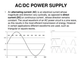
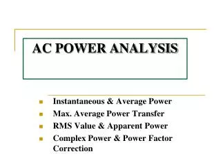
AC POWER ANALYSIS. Tunku Muhammad Nizar Bin Tunku Mansur Pegawai Latihan Vokasional Pusat Pengajian Kejuruteraan Sistem Elektrik. Content. Average Power Maximum Average Power Transfer Complex Power Power Factor Correction. AVERAGE POWER. Average Power.

E N D
AC POWER ANALYSIS Tunku Muhammad Nizar Bin Tunku Mansur Pegawai Latihan Vokasional Pusat Pengajian Kejuruteraan Sistem Elektrik
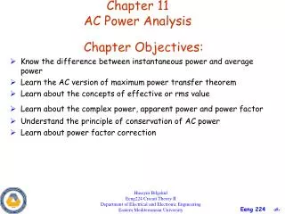
Content • Average Power • Maximum Average Power Transfer • Complex Power • Power Factor Correction
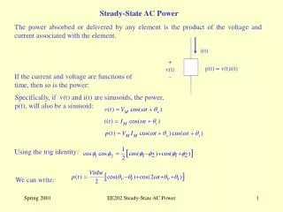
Average Power Average Power, in watts (W), is the average of instantaneous power over one period
Average Power Resistive load (R) absorbs power all the time. For a purely resistive circuit, the voltage and the current are in phase (v= i).
Average Power Reactive load (L or C) absorbs zero average power. For a purely reactive circuit, the voltage and the current are out of phase by 90o (v - i = ±90).
Exercise 11.3Find the average power supplied by the source and the average power absorb by the resistor
Solution The current I is given by The average power supplied by the voltage source is
Solution The current through the resistor is The voltage across resistor is The average power absorbed by the resistor is Notice that the average power supplied by the voltage source is same as the power absorbed by the resistor. This result shows the capacitor absorbed zero average power.
Practice Problem 11.3Calculate the average power absorbed by the resistor and the inductor. Then find the average power supplied by the voltage source
Solution The current I is given by For the resistor
Solution For the inductor The average power supplied by the voltage source is Notice that the average absorbed by the resistor is same as the power supplied by the voltage source. This result shows the inductor also absorbed zero average power.
Maximum Power Transfer For maximum power transfer, the load impedance ZL must equal to the complex conjugate of the Thevenin impedance Zth
Maximum Average Power The current through the load is The Maximum Average Power delivered to the load is
Maximum Average Power By setting RL = Rth and XL = -Xth , the maximum average power is In a situation in which the load is purely real, the load resistance must equal to the magnitude of the Thevenin impedance.
Exercise 11.5Determine the load impedance ZL that maximize the power drawn and the maximum average power.
Solution First we obtain the Thevenin equivalent To find Zth, consider circuit (a) To find Vth, consider circuit (b)
Solution From the result obtained, the load impedance draws the maximum power from the circuit when The maximum average power is
Practice Problem 11.5Determine the load impedance ZL that absorbs the maximum average power. Calculate the maximum average power.
Solution First we obtain the Thevenin equivalent To find Zth, consider circuit (a) To find Vth, consider circuit (b) By using current divider
Solution From the result obtained, the load impedance draws the maximum power from the circuit when The maximum average power is
Example 11.6Find the value of RL that will absorbs maximum average power. Then calculate that power.
Solution First we obtain the Thevenin equivalent Find Zth Find Vth By using voltage divider
Solution The value of RL that will absorb the maximum average power is The current through the load is The maximum average power is
Practice Problem 11.6Find the value of RL that will absorbs maximize average power, Then calculate the power.
Solution First we obtain the Thevenin equivalent To find Zth let and Then To find Vth By using voltage divider
Solution The value of RL that will absorb the maximum average power is The current through the load is The maximum average power is
Complex Power • Apparent Power, S (VA) • Real Power, P (Watts) • Reactive Power, Q (VAR) • Power Factor, cos
Complex Power • Complex power is the product of the rms voltage phasor and the complex conjugate of the rms current phasor. • Measured in volt-amperes or VA • As a complex quantity • Its real part is real power, P • Its imaginary part is reactive power, Q
Complex Power (Derivation) From derivation, we notice that the real power is or and also the reactive power or
Real or Average Power • The real power is the average power delivered to a load. • Measured in watts (W) • The only useful power • The actual power dissipated by the load
Reactive Power • The reactive power, Q is the imaginary parts of complex power. • The unit of Q is volt-ampere reactive (VAR). • It represents a lossless interchange between the load and the source • Q = 0 for resistive load (unity pf) • Q < 0 for capacitive load (leading pf) • Q > 0 for inductive load (lagging pf)
Apparent Power • The apparent power is the product of rms values of voltage and current • Measured in volt-amperes or VA • Magnitude of the complex power
Power Factor • Power factor is the cosine of the phase difference between voltage and current. • It is also cosine of the angle of the load impedance.
Power Factor • The range of pf is between zero and unity. • For a purely resistive load, the voltage and current are in phase so that v- i = 0 and pf = 1, the apparent power is equal to average power. • For a purely reactive load, v- i = 90and pf = 0, the average power is zero.
Power Triangular Comparison between the power triangular (a) and the impedance triangular (b).
Problem 11.46 • For the following voltage and current phasors, calculate the complex power, apparent power, real power and reactive power. Specify whether the pf is leading or lagging. • V = 22030o Vrms, I = 0.560o Arms. • V = 250-10o Vrms, I = 6.2-25o Arms. • V = 1200o Vrms, I = 2.4-15o Arms. • V = 16045o Vrms, I = 8.590o Arms.
Solution a) S = VI* = (22030o)(0.5-60o) = 110-30o VA = 95.26 – j55 VA Apparent power = 110 VA Real Power = 95.26 W Reactive Power = -55 VAR pf is leading because current leads voltage b) S = VI* = (250-10o)(6.225o) = 155015o VA = 1497.2 + j401.2 VA Apparent power = 1550 VA Real Power = 1497.2 W Reactive Power = 401.2 VAR pf is lagging because current lags voltage c) S = VI* = (1200o)(2.415o) = 28815o VA = 278.2 + j74.54 VA Apparent power = 288 VA Real Power = 278.2 W Reactive Power = 74.54 VAR pf is lagging because current lags voltage d) S = VI* = (16045o)(8.5-90o) = 1360-45o VA = 961.7 – j961.7 VA Apparent power = 1360 VA Real Power = 961.7 W Reactive Power = -961.7 VAR pf is leading because current leads voltage
Problem 11.48 Determine the complex power for the following cases: • P = 269 W, Q = 150 VAR (capacitive) • Q = 2000 VAR, pf = 0.9 (leading) • S = 600 VA, Q = 450 VAR (inductive) • Vrms = 220 V, P = 1 kW, |Z| = 40 (inductive)
Solution • Given P = 269W, Q = 150VAR (capacitive) • Complex power, b) Given Q = 2000VAR, pf = 0.9 (leading) Complex power,
Solution c) Given S = 600VA, Q = 450VAR (inductive) Complex power,
Solution d) Given Vrms = 220V, P = 1kW, |Z| = 40 (inductive) Complex power,
Problem 11.42 • A 110Vrms, 60Hz source is applied to a load impedance Z. The apparent power entering the load is 120VA at a power factor of 0.707 lagging. Calculate • The complex power • The rms current supplied to the load. • Determine Z • Assuming that Z = R + j L, find the value of R and L.
Solution Given S = 120VA, pf = 0.707 = cos = 45o a) the complex power b) the rms current supplied to the load
Solution c) the impedance Z d) value of R and L If Z = R + jL then Z = 71.278 + j 71.278
Problem 11.83 • Oscilloscope measurement indicate that the voltage across a load and the current through is are 21060o V and 825o A respectively. Determine • The real power • The apparent power • The reactive power • The power factor