Download
1 / 1
10 likes | 197 Views
Blower Door Testing of Insulated Concrete Form (ICF) Homes. Marzena Kasia FYDRYCH 1 , Michael STREET 1,2 , Lori FERRIS 1, Leslie NORFORD 1

E N D
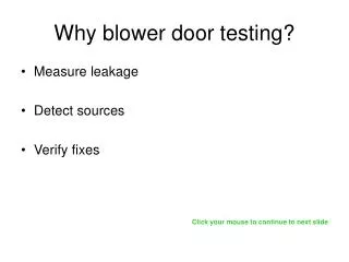
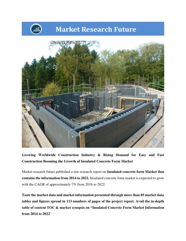
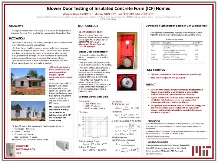
Blower Door Testing of Insulated Concrete Form (ICF) Homes MarzenaKasia FYDRYCH1, Michael STREET1,2, Lori FERRIS1,Leslie NORFORD1 1Department of Civil and Environmental Engineering, Massachusetts Institute of Technology, 77 Massachusetts Ave, 02139 Cambridge, United States. 2 Morehouse College ,Atlanta, GA mfydrych@mit.edu OBJECTIVE METHODOLOGY Construction Classification Based on Unit Leakage Area[4] The objective of this part of the project is to evaluate the air tightness of Insulated Concrete Form single-family houses using Blower Door Test. • BLOWER DOOR TEST • Blower door tests have been performed by certified home auditors according to ASTM E1827-96[1] or ASTM E779-03[2] using the Minneapolis Blower Doorwith TECTITE software. • Blower Door Methodology[3] • A powerful variable speed fan is placed in an opening in the building envelope • The air is blown into (pressurization) or out of (depressurization) the building. • A uniform, artificial, static pressure is imposed across the entire building envelope and the amount of air being moved by the fan to create this pressure differential is determined. • The air flow rate through the fan is usually determined from: • a) measurements of the pressure drop across a known flow restriction, or • b) the fan rotational speed and a calibration curve. Leakage area normalized by exposed surface area is a useful metric for evaluating air tightness, based on ASHRAE ratings. MOTIVATION • Infiltration of air through the building envelope is often a major variable in a system’s heating and cooling loads. • Air flows through building elements such as walls, roofs, windows, doors and bathroom and kitchen vents. The choice of walls, windows and doors materials and the quality of construction affect the total leakage area of the envelope. Air flow depends on the envelope’s leakage area and the pressures generated by buoyancy forces (associated with indoor-outdoor temperature differences) and wind. These natural forces vary with building location. • ICF walls consist of a solid, continuous and seamless unit that suggests tighter construction than framed walls. • Infiltration is very difficult to predict and is better estimated with house-specific air tightness tests. Inadequate field tests have been done to evaluate the general potential for reduced air infiltration of ICF homes. KEY FINDINGS • Tightness of tested ICF houses varied from good to tight. • Mean unit leakage area was 0.016in2/ft2 IMPACT B • Measurement-based air tightness metrics indicate that ICF houses are subject to lower amounts of uncontrolled outdoor airflow than typical production housing. • Tighter construction facilitates the use of mechanical ventilation with heat recovery for low-cost and low-environmental-impact building ventilation. • Air tightness measurements allow us to quantify energy use and carbon emissions associated with air leakage for houses in different climate regions using building energy simulation programs. Example Blower Door Data Building Data 1782.5 ft2 floor area 14082.1 ft3 volume 3962 ft2 exposed surface Calculations Air Change per Hour MIT in cooperation with the concrete industry has scheduled air tightness tests of 40 ICF houses across the United States. Flow at 4Pa Test Data AL total leakage area of the building REFERENCES [1] ASTM E1827-96 Determining Airtightness of Buildings Using an Orifice Blower Door [2] ASTM E779-03 Standard Test Method for Determining Air Leakage Rate by Fan Pressurization [3] ASHRAE 438RP-92 Evaluation of the Techniques for the Measurement of Air Leakage ofBuilding Components, D.G.Colliver, W.E.Murphy, W.Sun [4] ASHRAE Fundamentals - 2009 • To date,15 blower door experiments have been carried out in: • Mississippi – 10 houses • Florida – 2 houses • Connecticut – 2 houses • New Hampshire – 1 house • House floor area varies from 800 to 7300ft2 Unit leakage area (per ft2 of exposed surface) Building Leakage Curve ACKNOWLEDGEMENTS This work has been supported by the Concrete Sustainability Hub at MIT, with sponsorship provided by the Portland Cement Association (PCA) and the RMC Research & Education Foundation. CONCRETE SUSTAINABILITY HUB Airflow at 50 Pascals