Download
1 / 34
360 likes | 1.05k Views
CE 260 SURVEYING. CHAPTER 5. THEODOLITES. General Background: Theodolites or Transits are surveying instruments designed to precisely measure horizontal and vertical angles. THEODOLITES. They are used to establish straight and curved lines. To establish or measure distance (Stadia)

E N D
CE 260SURVEYING CHAPTER 5
THEODOLITES • General Background: • Theodolites or Transits are surveying instruments designed to precisely measure horizontal and vertical angles.
THEODOLITES • They are used to establish straight and curved lines. • To establish or measure distance (Stadia) • To establish Elevation when used as a level. (When we set the vertical angle to 90°).
TRANSITS They have: • 4 screw level base. • Metallic vertical and horizontal circles read with Vernier scale. • Plumb Bob • Low precision • Old instrument. Not in use now.
THEODOLITES They have: • 3 screw level base • Glass horizontal and vertical circles, read directly or through micrometer. • Right angle prism (optical plummet) • High precision
ELECTRONIC THEODOLITE • Electronic read out 1” eliminate mistakes and reading the angles. • Precision varies from 0.5” – 20” • Zero is set by a button. • Repeated angle averaging. • Replacing optical theodolites (It is less expensive to purchase and maintain).
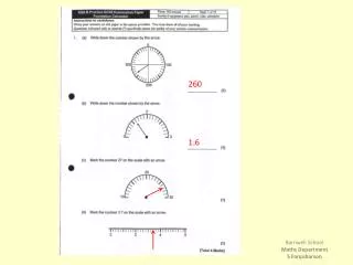
THEODOLITES Top image shows the Electronic Theodolite. Bottom shows the Scale readings.
THEODOLITES • ELECTRONIC THEODOLITE DETAILS
THEODOLITES • OPERATION KEYS AND DISPLAYS
THEODOLITES • Field noted for repeated angles
THEODOLITES SET-UP • Place the instrument over the point with the tripod plate as level as possible and with two tripod legs on the downhill side, if applicable. • Stand back a pace or two and see if the instrument appears to be over the station; if it does not, adjust the location and check again from a pace or two away.
THEODOLITES SET-UP 3. Move to a position 90° opposed to the original inspection location and repeat step 2. 4. Check that the station point can now be seen through the optical plummet (or that the laser plummet spot is reasonably close to the setup mark). Then push the tripod legs firmly by pressing down on the tripod shoe spurs.
THEODOLITES SET-UP 5. While looking through the optical plumb (or at the laser spot), manipulate the leveling screws (one, two or all the three at a time) until the cross hair (bull’s-eye) of the optical plummet or the laser spot is directly on the station mark. 6. Level the theodolite circular bubble by adjusting the tripod legs up or down.
THEODOLITES SET-UP 7. Perform a check through the optical plummet or note the location of the laser spot to confirm that it is still quite being over the station mark. 8. Turn one (or more) leveling screws to be sure that the circular bubble is now exactly centered (if necessary).
THEODOLITES SET-UP 9. Loosen the tripod clamp bolt a bit and slide the instrument on the flat tripod top (if necessary) until the optical plummet or laser spot is exactly centered on the station mark. Retighten the tripod clamp bolt and reset the circular bubble, if necessary.
THEODOLITES SET-UP 10. The instrument can now be precisely leveled by centering the tubular bubble. Set the tubular bubble so that it is aligned in the same direction as two of the foot screws. Turn these two screws (together or independently) until the bubble is centered. Then turn the instrument 90°, at which point the tubular bubble will be aligned with the third leveling screw.
THEODOLITES SET-UP 10. Next, turn that third screw to center the bubble. The instrument now should be level, although it is always checked by turning the instrument through 180°.
THEODOLITES Repeating optical theodolite: • Has 3 leveling screws • Optical plummet, light weight, glass circle, micrometer (to read the angles). • Most theodolites are equipped with compensating device (automatic horizontal). • 90° or 270° vertical angle of horizon.
THEODOLITES • Micrometer used to read vertical and horizontal angles. • 2 independent motion (upper and lower). If you move the upper motion, then the angle does not change. But if you move the lower motion, the angle will change.
DIRECT OPTICAL THEODOLITE • Has only one motion (upper). To find angle: • Read the initial direction (L target) • Read the final direction (R target) • Determine the difference between the two.
DIRECT OPTICAL THEODOLITE • Direct optical theodolite generally is more precise. Some models can read directly 0.2” and estimate 0.1”. • Several sightings are required for precise work. • Distribute initial reading around the circle to minimize the effect of circle graduation distribution, so initial reading read 0, 45,90,135,…
LAYING OFF ANGLES • The angle is to be laid out no more precisely than the least count of the transit or theodolite.
LAYING OFF ANGLES • Process: Lock angle, rotate theodolite, then open lock and measure again same angle. Should have double the first angle measurement.
PROLONGING A STRAIGHT LINE • Start by taking distance at A. Then go to B, rotate 180°, look back at A, plunge and make another line towards C.
BUCKING IN (INTERLINGING) • Read A, then plunge to B. If Distance between B and B’ is 1 M, then you have to move 0.5 M to find C. then do the sighting again.
INTERSECTION OF 2 STRAIGHT LINES • Put 2 strings between points and then get the intersection.
PROLONGING A MEASUREMENT LINE BY TRIANGULATION OVER AN OBSTACLE
PROLONGING A LINE PAST AN OBSTACLE There are 3 methods for it: • Right-angle offset method. • Random-line method. • Triangulation method.
THE END OF CHAPTER 5 • THANK YOU!