Download
1 / 12
130 likes | 312 Views
Drum Phase Adjustment. On Previous models, a patch was embedded on the surface of the Drum A reflective sensor would monitor this patch to adjust drum phase. Drum Phase was adjusted for Cyan, Magenta, and Yellow (relative to black) separately.

E N D
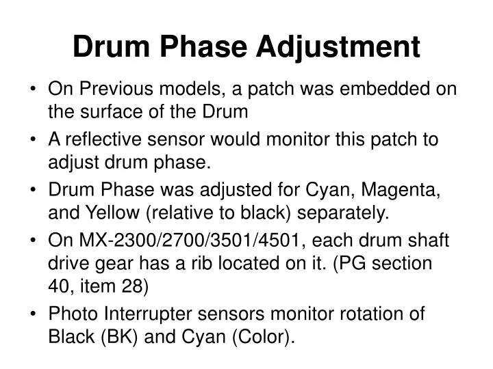
Drum Phase Adjustment • On Previous models, a patch was embedded on the surface of the Drum • A reflective sensor would monitor this patch to adjust drum phase. • Drum Phase was adjusted for Cyan, Magenta, and Yellow (relative to black) separately. • On MX-2300/2700/3501/4501, each drum shaft drive gear has a rib located on it. (PG section 40, item 28) • Photo Interrupter sensors monitor rotation of Black (BK) and Cyan (Color).
Drum Drive Gear RIB
Drum Phase Sensors Black Color
Drum Phase Adjustment • On MX-2300/2700/3501/4501 Imagers, there are only 2 Drum motors. • 1 Black motor (provides drive to K) • 1 Color motor (provides drive to C,M,Y) • Phase detect sensor (BK) monitors Black. (DHPD_K) • Phase detect sensor (C) monitors Cyan. (DHPD_CL) • Since C,M,Y drums are driven by same motor, Cyan represents rotation for all 3.
Drum Phase Adjustment • In simulation 50-22, Color Registration and Drum phase Adjustment can be done Simultaneously. This is the recommended method. • In Simulation 50-22, select ALL. (Automatic) • If 50-22 produces unsatisfactory results for drum phase, do the manual drum phase adjustment, simulation 44-31.
Simulation 44-31 • If 50-22 automatic adjustment is unacceptable, perform 44-31 Manual Drum Phase adjustment. • Before doing Manual Drum Phase adjustment, “DM_PHASE” must be disabled in Simulation 44-1. (not highlighted) • Set value “A” to 1, and value “C” to select a cassette containing 11x17” paper. • Select EXECUTE. 8 pages will be output, numbered 1 through 8. • Choose the printout that looks best, (color lines that are straightest) • Enter the number printed on the page to value “B”.
Troubleshooting • If Drum Motors fail, Drum Phase error codes will result. (There are no error codes that specifically identify drum motor failure.) • F2-”xx” occurs, and copying is NOT prohibited. (DV units and transfer belt will continue to rotate.) • Depending on which motor fails, the resulting copies will exhibit an absence of Black, or an absence of Cyan, Magenta, and Yellow.
Troubleshooting F2-50 Error: K phase sensor sensing trouble. • Check Connector to Sensor • Check for dirt on Sensor • Check rib on BLACK drum drive gear for damage. If OK, replace the sensor. • Use Simulation 30-1 “DHPD_K” to check for change of state of the sensor • Check PCU PWB at CN12, pin 32, DHPD_K • Confirm rotation of BLACK flywheel when copying.
Troubleshooting F2-51 Error: CL phase sensor sensing trouble. • Check Connector to Sensor • Check for dirt on Sensor • Check rib on CYAN drum drive gear for damage. If OK, replace the sensor. • Use Simulation 30-1 “DHPD_CL” to check for change of state of the sensor • Check PCU PWB at CN12, pin 31, DHPD_CL • Confirm rotation of COLOR flywheels when copying.