Download
1 / 27
280 likes | 589 Views
W650 Wind Generator Protection System . System Protection & Improved Operational Uptime. Why W650?. Protection to Provide Backup to Wind Turbine Controls & Excitation Better Wind Farm Economics by Improving System Uptime & Time to Restoration

E N D
W650 Wind Generator Protection System System Protection & Improved Operational Uptime
Why W650? • Protection to Provide Backup to Wind Turbine Controls & Excitation • Better Wind Farm Economics by Improving System Uptime & Time to Restoration • Address Lack of Wind Turbine & System Event Diagnostics Diagnostic in W650 can tell what happened, why, and when … to the mSec
What is the W650? • Part of an Overall Protection System … but can be used as a stand alone protective device • Overlay to Existing Wind Turbine & Farm Control by Providing Unit Protection, Wind Farm System Protection, Unit, & System Diagnostics Substation Protection Controller W650 1 in Wind Turbine Windfarm Substation Protection Controller sends Trip and Block Commands to and From W650’s W650’s can also send trip and block commands to each other W650 2 in Wind Turbine W650 n in Wind Turbine
G G G G G G G G G G G G G G G G G G G G G G G G G Definition of Larger Wind Farm System (Units > 1MW on a Coordinated Farm) Utility (e.g. 33kV) Tie Breaker Line Transformer Breaker Step Up Transformer Bus Breaker Bus Windfarm Substation Collector Feeder Breakers Collector Bus
WTG Definitions with Wind Turbine Wind Tower Wind Tower Breaker Collector System Voltage (e.g. - 3kV or 13.8 … depends on MW size of Generator & Presence Transformer) Transformer Generator Output Voltage (e.g. - 575V or 3kV … depends on MW size of Generator) Excitation Generator
Inside the Wind Turbine Tower Cable Transformer Faults Wiring Inside the Electrical Distribution Panel Wind Turbine Generator Excitation System Fault On the Wind Farm Collector Bus Cable Fault Step Up Transformer Substation Bus Structure Fault Feeder Fault Impact on Stability External to the Wind Farm Voltage Stability Reverse Power Flow Sources of Faults
How Faults Manifest Themselves • Inside the Wind Turbine • IOC, TOC, Ground Fault • On the Wind Farm • Voltage/Current Unbalance • External to the Wind Farm • IOC, TOC, Voltage Stability
Subjects for Discussion … Gaps Today • No backup Protection in Wind Turbines/Towers … Need for a System Wide Protective Application apart from Control • Lack of Coordinated Event Record & Oscillography make it Difficult to Determine What Happened & When, resulting in Prolonged Time to Return to Service • Lack of Overall Coordinated Wind Farm System Protection can result in Lack of Operational Selectivity and Reduced System Uptime
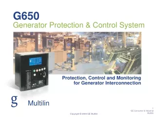
W650 Wind Turbine Protection Capabilities Configurable Display & LED’s • W650 for Protection, Metering, and Coordination to Upstream Substation Protection • Communications to GE Wind Turbine Controller via CANopen protocol • Available Protection – Under/overvoltage, Under/overfrequency, voltage unbalance, directional over-current, zero sequence overvoltage, aux voltage, and breaker failure Keypad & Shuttle Front Port Upload & Download
W650 Hardware Construction The W650 features advantage such as: • Modular hardware architecture: • Main CPU board with two plug and play comm boards • Universal magnetic (CTs & VTs) module • Programmable I/O module • Single or redundant power supply • Front board: HMI ( Graphical or alphanumerical display, LEDs, RS232) • Modern and open communication protocols for easy integration
W650 Wind Turbine Protection (con’t) • Metering – current (+/- 0.5%), voltage (+/- 1%), power(+/-1%), energy (1%), power factor (0.02) • Event capture – up to 479 events time stamped to 1mSec • Oscillography – Up to 20 oscillography files programmable from 4-64 samples/cycle, 1MB of data, analog and digital signals. Retrievable via front panel or system communications. • Monitoring – 4x20 character display … optional graphic display …
W650 Wind Turbine Protection (con’t) • Control – programmable unit control • Communications – IEC61850 communications to peer W650’s and Substation Protection Relays Substation Protection Controller W650 1 in Wind Turbine IEC61850 Communications Protocol Uses Ethernet to Send Block and Trip Commands from WTG Relays to Substation Controller as well as via Peer to Peer W650 2 in Wind Turbine W650 n in Wind Turbine
How does the W650 Integrate into the Entire Wind Farm?
Examples of Wind Farm Protection Requirements • Open Collector Breakers Upon Fault in Cable to Host Utility • All Wind Turbines, Selective, or Entire Collector • Open Collector Breakers Upon Transformer Fault • All Wind Turbines, Selective, or Entire Collector • Collector Bus Cable fault Requires Selective Trip Wind Turbine Breakers • Issues in a Specific Wind Turbine to Prompt Block Command to Other Wind Turbines
Electrical Protection Topology Interconnect Protection GSU Protection Bus Protection Feeder Protection Feeder Protection Feeder Protection Feeder Protection Turb. Prot. Turb. Prot. Turb. Prot. Turb. Prot. Turb. Prot. Turb. Prot. Turb. Prot. Turb. Prot. Turb. Prot. Turb. Prot. Turb. Prot. Turb. Prot.
Network Topology Interconnect Protection GSU Protection Bus Protection Feeder Protection Feeder Protection Feeder Protection Feeder Protection Ethernet Switch Turb. Prot. Feeder 2 Feeder 3 Feeder 4 Enet Switch Protection System Overlays Parallel Control System Turb. Prot. Enet Switch • Fault Tolerant Ring • Support WTG outside a break in the ring • Requires 2 Fiber Strands • Worst case 1 micro Sec Delay by Switch • Unmanaged Switch in WTG • Managed Switch w/VLAN in Substation Turb. Prot. Enet Switch
Alternate Network Topology (if 3rd Party Wind Farm Protection is Used) Other Supplier’s Protection Hardwired IO Sub controller Ethernet Switch Turb. Prot. Feeder 2 Feeder 3 Feeder 4 Enet Switch Turb. Prot. Enet Switch Turb. Prot. Enet Switch
Transfer Trip Capabilities of W650 • send a “block” or “transfer trip” from the protection offering in the Wind Farm substation protection (GE or other) to entire collector bus or individual wind turbine • “block” or “transfer trip” command from individual wind turbine to substation protection
Transfer Trip Example • Transformer Protection detects Differential Fault and Initiates Transfer Trip Command • Transformer Breaker Opens • Collector Bus W650’s Receive Transfer Trip Command and Issue Command to Trip Breaker • Collector Bus and WTG’s Isolated
Yellow Items Represent Customer Specific Variables Payback Calculated on Improved System Operations Equipment/Personnel Damage Avoidance Not Included Economics
Support Resources Available from GE Multilin • Available On-line at www.gemultilin.com • Product Cut Sheet • Product Presentation • Whitepaper on Transfer Trip Technologies and Benefits • Guideform Specification to Assist Consultants and EPC’s • Wiring/Installation Information • Pricing and Ordering Information Available On-Line
Ordering Information • Greenfield Installations • Specify to Wind Turbine OEM & Wind Farm EPC • Request to Include with Wind Farm Substation and Wind Turbine’s • Field Integration Services Available • Retrofit Bill of Material • 1 W650 per Wind Turbine • 1 Ethernet Switch per Wind Turbine (GE Multilin model ML600) • 1 Ethernet Switch in Wind Farm Substation (GE Multilin model ML2400) • Substation Protection Controller (GE Multilin C30)
Who to Contact for Questions • GE Multilin – John Garrity, 518.877.8860, john.garrity@ge.com • GE PSEC – tbd • GE Wind - tbd