Download
1 / 66
690 likes | 933 Views
INVERTER-Y TRAINING 2009. TOPICS. Introduction to Y-Inverter Control Algorithm Troubleshooting. INTRODUCTION. INTRODUCTION. What is inverter ? What are the advantages ? Differences between Conventional & Inverter A/C Basics of Inverter Technology. INTRODUCTION. What is Inverter?.

E N D
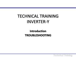
INVERTER-Y TRAINING 2009
TOPICS Introduction to Y-Inverter Control Algorithm Troubleshooting
INTRODUCTION • What is inverter ? • What are the advantages ? • Differences between Conventional & Inverter A/C • Basics of Inverter Technology
INTRODUCTION What is Inverter? • Electrical supply has fix frequency • Inverter type air conditioner have frequency changer which can change the electrical frequency to control the speed of the compressor • This in turn, can control the capacity accordingly
INTRODUCTION Advantages • Enhanced room temperature comfort - More precise room temperature control - Temperature fluctuation is kept within ± 0.5C from set temperature Conventional Inverter
INTRODUCTION Conventional compressor Compressor capacity Full capacity Time Advantages • Less on / off cycle Room temperature control: switching compressor ON & OFF Compressor capacity Inverter Room temperature control: Control compressor rotational speed smoothly Smooth ramp up from zero to high rotational speed Slow down as temperature drops Maintain room temperature at low speed Time
INTRODUCTION Advantages • Starting frequency Compressor frequency (rps) 1.0 hp – 68 rps 1.5 hp – 74 rps Max. 55 35 Target frequency 20 0 Time (min) 2 1 6
INTRODUCTION Advantages • Fast cooling Conventional non-inverter A/C Inverter A/C Room temperature Set temperature Time Quick cooling
INTRODUCTION Advantages • Low starting current Running current Conventional A/C: • High starting current • Frequent on/off cycle Inverter A/C: • Low starting current • Smooth operation Hours of operation
INTRODUCTION Advantages • Higher reliability • Less compressor start – stop cycle • Low starting current • Longer compressor motor lifespan
INTRODUCTION Advantages • Low energy consumption with superior efficiency • Frequency of supply current is varied according to load requirements – excellent efficiency • Range is between 0 – 68 rps (204 Hz) for 1.0 hp 0 – 74 rps (222 Hz) for 1.5 hp • Resulting in significantly LESS compressor start/stop – low energy consumption Lowest operating frequency = 60 Hz
INTRODUCTION Advantages • Protection Additional software protection against • Over current • Over heating
INTRODUCTION Differences Overview
INTRODUCTION Energy Savings Creation of Comfort Basics of Inverter Technology Inverter-driven Compressor IPM (Inverter Power Module) Electronic Expansion Valve (EXV)
INTRODUCTION Basics of Inverter Technology Power supply Rectifier circuit Compressor Motor IPM Adjust capacity according to actual load by • Controlling the EXV opening • Controlling the refrigerant flow
INTRODUCTION Compressor Energy Source Rectifying Circuit Inverter Circuit Control & Protection Circuitry Feedback Basics of Inverter Technology Inverter system block diagram
INTRODUCTION Basics of Inverter Technology Inverter drive power circuit IN U M V OUT W Rectifier Inverter
INTRODUCTION Basics of Inverter Technology What are Rectifier / Inverter? Rectifier: Rectifying with smoothing Changing AC DC Inverter: Inverse transformation with P.W.M. Changing DC AC
INTRODUCTION IN U M V OUT W Basics of Inverter Technology Inverter drive power circuit - components IPM(Inverter Module) Reactor Diode Electrolytic capacitor
INTRODUCTION t1 50 Hz Basics of Inverter Technology The system Inverter Output Frequency 222 Hz 60 Hz Power supply Input frequency 50Hz Inverter AC/DC Rectifier DC/AC Inverter u t t 222 Hz 60 Hz compressor motor input IPM
INTRODUCTION Basics of Inverter Technology Indoor PCB
INTRODUCTION Basics of Inverter Technology Outdoor PCB
The compressor is frequency-controlled during normal operation. The target frequency is set based on following parameters: i) Outdoor ambient temperature ii) Set temperature iii) Room temperature When the frequency increases, the rotation speed of compressor increases resulting in an increased refrigerant circulation, this lead to higher amount of heat transfer and vice versa when frequency decreases. Frequency Principle CONTROL ALGORITHM
The system has 2 operating modes. The mode selection is done in Inverter (indoor) controls. The operating modes are: Cool Fan Operating Modes CONTROL ALGORITHM
CONTROL ALGORITHM Function – Cool Mode • When Tr >= Ts – 1.5°C - Comp, ID Fan and OD Fan ON • When Tr <= Ts - 2°C - Comp and OD Fan OFF - ID Fan remain ON Tr = Room Temperature Ts = Set Temperature
At beginning of cooling operation, compressor frequency will be increased smoothly to the target frequency so that the room temperature is reduced. When set temperature is achieved, operation frequency will be reduced to stabilize the room temperature. Function – Cool Mode CONTROL ALGORITHM
CONTROL ALGORITHM When will Compressor Stop? • When cooling load is too small, even with lowest operation frequency and the room temperature still fall below compressor cut off point, compressor will stop. Compressor Capacity Lowest Freq Time Tr <= Ts - 2°C Comp will stop
Function - Fan Mode Only High, Medium and Low fan speeds are allowed. When changing cool mode to fan mode, the compressor will stop and OD fan stops after 30s. Compressor will only ON if the minimum stop time is > 3 minutes and the user change back to cool mode. Fan speed will maintain same as during fan mode. CONTROL ALGORITHM
Master by outdoor unit. Indoor controller board will transmit signal to outdoor controller board every 0.5s. Outdoor unit will response to indoor once the valid data is received. PROTECTION Indoor Acknowledge Send Signal Outdoor Protection Control - Data Communication Error Between Indoor and Outdoor
If the data communication line between indoor and outdoor occurs error for 15scontinuously, compressor will stop, OD fan stop after 30s. ID LED blinks error. If the communication resumes after 15s, error code is clear and compressor restarts after 3 minutes. If the communication is not resume after 15s, unit unable to restart and the error keep blinking. PROTECTION Protection Control - Data Communication Error Between Indoor and Outdoor
Indoor Coil Frost Prevention Only available in cooling mode. When the indoor coil temperature < 2°C, the compressor starts to drop the frequency. This protection is activated when: - Indoor coil temperature < 0°C for more than 180s. Compressor will stop, OD fan stop after 30s and indoor fan can only run at super low fan speed. The unit can only be restarted after 3 minutes. When the indoor coil temperature >13°C, the compressor frequency will be reset based on the OD ambient, room and set temperature. PROTECTION
Input Current Control PROTECTION
Input Current Control When the input current for running compressor exceeds I2, running frequency will be reduced by 1 step. If current still exceeds I2, frequency will be reduced by another 1 step until total current falls between I2 and I3. This protection is activated when the input current exceeds I1 for 2 seconds. Compressor will stop and it is considered total current overload. The unit can only be restarted after 3 minutes. If input current <I3, the compressor frequency is reset based on the OD ambient, set and room temperature. PROTECTION
Compressor Discharge Temperature Control PROTECTION
If compressor discharge temperature >102°C, running frequency will be reduced by 1 step. If compressor discharge temperature still >102°C, frequency will be reduced by another 1 step until temperature falls between 99°C and 90°C. This protection is activated when the compressor discharge temperature > 110°C. The compressor will stop and considered trip. The unit can only be restarted after 3 minutes. If the compressor discharge temperature < 90°C, the compressor frequency will be reset based on the OD ambient, set and room temperature. PROTECTION Compressor Discharge Temperature Control
PROTECTION High Pressure Protection
The compressor frequency is adjusted depend on the coil temperature. This protection is activated when the outdoor coil temperature > 64°C, the compressor stop and OD fan stop after 30s. The unit can only be restarted after 3 minutes. PROTECTION High Pressure Protection
Protection on the IPM IPM error is declared when; i) Compressor’s motor peak current > 21A OR ii) IPM temperature >100°C OR iii) IGBT peak current > 16A. PROTECTION IPM error
TROUBLESHOOTING Fault display by indoor unit When any error occurs, indoor LED display will keep blinking LED blinks here
TROUBLESHOOTING Fault diagnosis by remote controller TIMER CANCEL button Hold down ON TIMER CLR or OFF TIMER CLR for 5 seconds
TROUBLESHOOTING Fault diagnosis by remote controller Press TIMER CANCER repeatedly until ID buzzer produces long beep The handset temperature display section will indicate the error code Error code ID unit buzzer will produce long beep if the handset error code = unit error A short and two consecutive beeps is not the unit error
TROUBLESHOOTING Fault diagnosis using outdoor 7-segment display
TROUBLESHOOTING Fault diagnosis using outdoor 7-segment display 7-segment display When there is no error, compressor running frequency is displayed, unit: rps Flashes error code when error occurs
TROUBLESHOOTING Fault diagnosis – stored last state error Remove battery from remote controller Replace battery again into remote controller Press Mode & ON/OFF buttons together Press Mode button to 5:00 Press ON/OFF once Repeat the fault diagnosis by remote controller steps Mode button TIMER CANCEL button ON/OFF button
TROUBLESHOOTING Error Codes
TROUBLESHOOTING Outdoor 7-segment display Press on the tact switch Display parameter by flashing of 7-segment Parameter 125, display as 25, follow by 01
TROUBLESHOOTING Equipments • Digital clampmeter • Digital multi-meter • Pressure gauge AC CURRENT RESISTANT AC VOLTAGE