Download
1 / 40
410 likes | 654 Views
Buckling of Columns 13.1-13.3. Buckling & Stability Critical Load. Introduction. In discussing the analysis and design of various structures in the previous chapters, we had two primary concerns:

E N D
Buckling of Columns 13.1-13.3 Buckling & Stability Critical Load
Introduction • In discussing the analysis and design of various structures in the previous chapters, we had two primary concerns: • the strength of the structure, i.e. its ability to support a specified load without experiencing excessive stresses; • the ability of the structure to support a specified load without undergoing unacceptable deformations.
Introduction • Now we shall be concerned with stability of the structure, • with its ability to support a given load without experiencing a sudden change in its configuration. • Our discussion will relate mainly to columns, • the analysis and design of vertical prismatic members supporting axial loads.
Introduction • Structures may fail in a variety of ways, depending on the : • Type of structure • Conditions of support • Kinds of loads • Material used
Introduction • Failure is prevented by designing structures so that the maximum stresses and maximum displacements remain within tolerable limits. • Strength and stiffness are important factors in design as we have already discussed • Another type of failure is buckling
Introduction • If a beam element is under a compressive load and its length is an order of magnitude larger than either of its other dimensions such a beam is called a columns. • Due to its size its axial displacement is going to be very small compared to its lateral deflection called buckling.
Introduction • Quite often the buckling of column can lead to sudden and dramatic failure. And as a result, special attention must be given to design of column so that they can safely support the loads. • Buckling is not limited to columns. • Can occur in many kinds of structures • Can take many forms • Step on empty aluminum can • Major cause of failure in structures
Buckling & Stability • Consider the figure • Hypothetical structure • Two rigid bars joined by a pin the center, held in a vertical position by a spring • Is analogous to fig13-1 because both have simple supports at the end and are compressed by an axial load P.
Buckling & Stability • Elasticity of the buckling model is concentrated in the spring ( real model can bend throughout its length • Two bars are perfectly aligned • Load P is along the vertical axis • Spring is unstressed • Bar is in direct compression
Buckling & Stability • Structure is disturbed by an external force that causes point A to move a small distance laterally. • Rigid bars rotate through small angles • Force develops in the spring • Direction of the force tends to return the structure to its original straight position, called the Restoring Force.
Buckling & Stability • At the same time, the tendency of the axial compressive force is to increase the lateral displacement. • These two actions have opposite effects • Restoring force tends to decrease displacement • Axial force tends to increase displacement.
Buckling & Stability • Now remove the disturbing force. • If P is small, the restoring force will dominate over the action of the axial force and the structure will return to its initial straight position • Structure is called Stable • If P is large, the lateral displacement of A will increase and the bars will rotate through larger and larger angles until the structure collapses • Structure is unstable and fails by lateral buckling
Critical Load • Transition between stable and unstable conditions occurs at a value of the axial force called the Critical Load Pcr. • Find the critical load by considering the structure in the disturbed position and consider equilibrium • Consider the entire structure as a FBD and sum the forces in the x direction
Critical Load • Next, consider the upper bar as a free body • Subjected to axial forces P and force F in the spring • Force is equal to the stiffness k times the displacement ∆, F = k∆ • Since is small, the lateral displacement of point A is L/2 • Applying equilibrium and solving for P: Pcr=kL/4
Critical Load • Which is the critical load • At this value the structure is in equilibrium regardless of the magnitude of the angle (provided it stays small) • Critical load is the only load for which the structure will be in equilibrium in the disturbed position • At this value, restoring effect of the moment in the spring matches the buckling effect of the axial load • Represents the boundary between the stable and unstable conditions.
Critical Load • If the axial load is less than Pcr the effect of the moment in the spring dominates and the structure returns to the vertical position after a small disturbance – stable condition. • If the axial load is larger than Pcr the effect of the axial force predominates and the structure buckles – unstable condition.
Critical Load • The boundary between stability and instability is called neutral equilibrium. • The critical point, after which the deflections of the member become very large, is called the "bifurcation point" of the system
Critical Load • This is analogous to a ball placed on a smooth surface • If the surface is concave (inside of a dish) the equilibrium is stable and the ball always returns to the low point when disturbed • If the surface is convex (like a dome) the ball can theoretically be in equilibrium on the top surface, but the equilibrium is unstable and the ball rolls away • If the surface is perfectly flat, the ball is in neutral equilibrium and stays where placed.
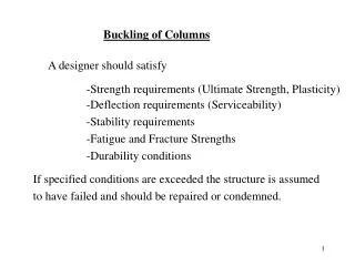
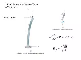
Critical Load • In looking at columns under this type of loading we are only going to look at three different types of supports: • pin-supported, • doubly built-in and • cantilever.
Pin Supported Column • Due to imperfections no column is really straight. • At some critical compressive load it will buckle. • To determine the maximum compressive load (Buckling Load) we assume that buckling has occurred
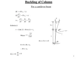
Pin Supported Column • Looking at the FBD of the top of the beam • Equating moments at the cut end; M(x)=-Pv • Since the deflection of the beam is related with its bending moment distribution
Pin Supported Column • This equation simplifies to: • P/EI is constant. • This expression is in the form of a second order differential equation of the type • Where • The solution of this equation is: • A and B are found using boundary conditions
Pin Supported Column • Boundary Conditions • At x=0, v=0, therefore A=0 • At x=L, v=0, then 0=Bsin(L) • If B=0, no bending moment exists, so the only logical solution is for sin(L)=0 and the only way that can happen is if L=n • Where n=1,2,3,
Pin Supported Column • But since • Then we get that buckling load is:
Pin Supported Column • The values of n defines the buckling mode shapes
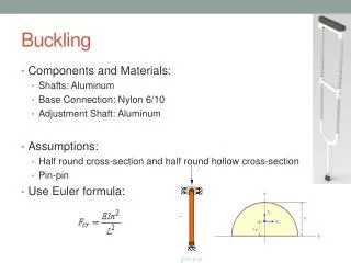
Critical Buckling Load • Since P1<P2<P3, the column buckles at P1 and never gets to P2 or P3 unless bracing is place at the points where v=0 to prevent buckling at lower loads. • The critical load for a pin ended column is then: • Which is called the Euler Buckling Load
Built-In Column • The critical load for other column can be expressed in terms of the critical buckling load for a pin-ended column. • From symmetry conditions at the point of inflection occurs at ¼ L. • Therefore the middle half of the column can be taken out and treated as a pin-ended column of length LE=L/2 • Yielding:
Cantilever Column • This is similar to the previous case. • The span is equivalent to ½ of the Euler span LE
Note on Moment of Inertia • Since Pcrit is proportional to I, the column will buckle in the direction corresponding to the minimum value of I
Critical Column Stress • A column can either fail due to the material yielding, or because the column buckles, it is of interest to the engineer to determine when this point of transition occurs. • Consider the Euler buckling equation
Critical Column Stress • Because of the large deflection caused by buckling, the least moment of inertia I can be expressed as • where: A is the cross sectional area and r is the radius of gyration of the cross sectional area, i.e. . • Note that the smallest radius of gyration of the column, i.e. the least moment of inertia I should be taken in order to find the critical stress.
Critical Column Stress • Dividing the buckling equation by A, gives: • where: • E is the compressive stress in the column and must not exceed the yield stress Y of the material, i.e. E<Y, • L / r is called the slenderness ratio, it is a measure of the column's flexibility.
Critical Buckling Load • Pcrit is the critical or maximum axial load on the column just before it begins to buckle • E youngs modulus of elasticity • I least moment of inertia for the columns cross sectional area. • L unsupported length of the column whose ends are pinned.