Download
1 / 62
1.03k likes | 3.03k Views
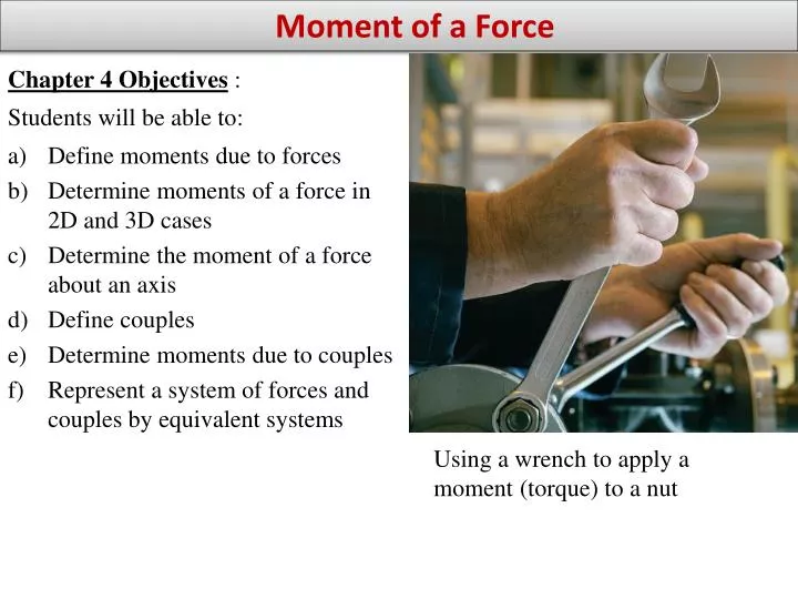
Moment of a Force. Chapter 4 Objectives : Students will be able to: a) Define moments due to forces Determine moments of a force in 2D and 3D cases Determine the moment of a force about an axis Define couples Determine moments due to couples

E N D
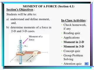
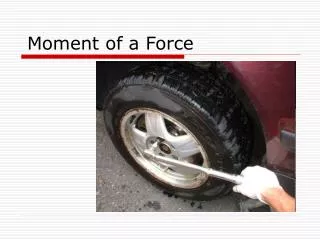
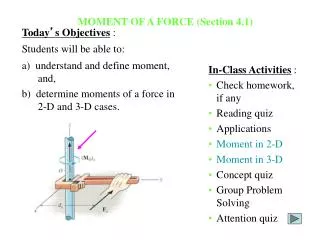
Moment of a Force • Chapter 4 Objectives : • Students will be able to: • a) Define moments due to forces • Determine moments of a force in 2D and 3D cases • Determine the moment of a force about an axis • Define couples • Determine moments due to couples • Represent a system of forces and couples by equivalent systems Using a wrench to apply a moment (torque) to a nut
APPLICATIONS Beams are often used to bridge gaps in walls. The location of force F has an impact on the values of the reactions at points A and B. Determining these reactions may involve calculating the moment due to force F on point A.
APPLICATIONS - The claw on the end of a hammer can be used to remove a nail.- How does the force applied on the handle (FH) affect the force on the nail (FN)?- This problem typically involves calculating the moments due to the forces about a point (point O for example).
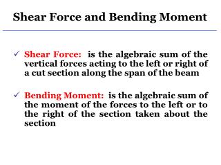
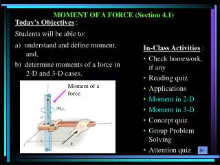
Moment of a Force about a Point - Section 4.1 The moment of a force about a point provides a measure of the tendency for rotation (sometimes called a torque).
Moment of a Force about a Point - (continued) • The moment of a force about a point: • Is a vector quantity, so it has both magnitude and direction. • For the 2D case, the magnitude of the moment is • d is the perpendicular distance from point O to the line of action of the force. • The direction of the moment is always in a direction that is perpendicular to the plane containing F and d. • For the 2D case, the direction of MO is either clockwise (CW) or counter-clockwise (CCW), depending on which way the object would tend to rotate
CROSS PRODUCT (Section 4.2) y x z Finding moments in 3D: Finding the perpendicular distance d between a force and a point in a 2D problem is fairly straightforward. This is more difficult in 3D. A different method is typically used in 3D – using a cross product. A cross product is a mathematical operation involving vectors. Cross products are used in various areas of engineering. In Statics, cross products are used to calculate moments in 3D problems. Let’s see how to find a cross product, then we will use it to find moments.
CROSS PRODUCT (Section 4.2) In general, the cross product of two vectors A and B results in another vector, C , i.e., C = A B. The magnitude of vector C is C = |A B|= A B sin The direction of C is perpendicular to the plane containing vectors A and B as determined using the right-hand rule. The result of the cross product can be expressed as a vector as follows: C = A B= A B sin uC where uCis the unit vector perpendicular to the plane containing vectors A and B. Using the RIGHT HAND RULE to show the direction of C
CROSS PRODUCT (continued) The right-hand rule is a useful tool for determining the direction of the vector resulting from a cross product. For example: i j = k Note that a vector crossed into itself is zero, e.g.,i i = 0
CROSS PRODUCT (continued) Memory Aid: + i j k i j k - • Cross product of Cartesian unit vectors: • Cross product in terms of rectangular coordinates Memory Aid:
CROSS PRODUCT (continued) Finding the cross product using a determinant. Each component can be determined using 2 2 determinants.
Example: Finding a cross product • Term by term • Using a determinant • Using a calculator (refer to the handout: "Cross and Dot Products“)
MOMENT OF A FORCE – VECTOR FORMULATION - (Section 4.3) Moments in 3D are generally calculated using a vector cross product. Using the vector cross product,MO = r F . Here r is the position vector from point O to any point on the line of action ofF.
MOMENT OF A FORCE – VECTOR FORMULATION (continued) So, using the cross product, a moment can be expressed as By expanding the above equation using 2 2 determinants (see Section 4.2), we get (sample units are N-m or lb-ft) MO = (ry FZ - rZ Fy) i - (rx Fz - rz Fx ) j + (rx Fy - ry Fx ) k
Properties of Cross Products • Properties of cross products: • are not commutative, • are distributive, • are not associative, Varignon’s Theorem: When the distributive property above is applied to calculating moments, it is sometimes called Varignon’s Theorem: Significance: If two forces act at a single point we can calculate the moment due to each force separately or find the moment due to the sum (resultant) of the forces.
Demonstration – Calculating moments in 2D Demonstration: Rope and wrench. Illustrate how the angle and location of rope affects the moment produced on the bolt. Example: Determine the moment about point A due to the 10 lb force applied to the wrench in each case below.
Common Torque Specifications Conversion Factors: 1 Nm = 8.8507 lbin = 0.73756 ftlb 1 lbft = 12.0 lbin = 1.3558 Nm 1 lbin = 0.083333 lbft = 0.11298 Nm
Common Torque Specifications (lb ft) (lb ft)
Torque Wrenches Ingersoll Rand Air Impact Wrench 3/8” Drive, 180 ft-lb Torque Park TW-2 Torque Wrench 3/8" drive, 0-600 in-lb Craftsman Microtork Torque Wrench 25-250 in-lb 3/8-in Drive Craftsman Electronic Torque Wrench, 3/8 in. Drive. Adjusts from 10 to 100 ft-lb
Calculating moments in 2D – 4 methods Calculation of moments in 2D – several approaches may be taken to calculate the moment about point A due to the force shown below: 1. Using F, the perpendicular () component of the force. MA = (d)(F) 2. Using d, the perpendicular () component of the distance. MA = (d)(F)
Calculating moments in 2D – 4 methods (continued) 3. Using rectangular components for F and d.MA = (dx)(Fy) + (dy)(Fx) • determine the sign of each part by inspection • CCW moments are + • CW moments are - 4. Using a cross product. This method is primarily used in 3D, but could be used in 2D problems also. We will come back to this method later.
EXAMPLE – Finding a moment in 2D. 30 100 lb 65 A • A 100 lb force is applied to an 18 inch bar as shown below. • Determine the moment about point A due to the 100 lb force by: • 1. Finding the perpendicular component of the force. • 2. Finding the perpendicular component of the distance. • Using rectangular components of the force and the distance. • Using a cross product.
EXAMPLE – Finding a moment in 2D Determine the moment about point A due to the 100 N force. Note: CW moments are negative and CCW moments are positive Solution Fy = – 100 (3/5) N Fx = 100 (4/5) N MO = {– 100 (3/5)N (5 m) – (100)(4/5)N (2 m)} N·m MO = – 460 N·m (or MO = 460 N·m CW)
EXAMPLE – Finding a moment in 2D A 13.2 N force P is applied to the lever which controls the auger of a snow blower. Determine the moment of P about a when a is equal to 30°.
EXAMPLE – Finding a moment in 2D • Determine the moment due to the three forces: • about point A on the beam • about point B on the beam
EXAMPLE – Finding a moment in 3D Find the moment due to force F about point O. Plan: 1) Find the position vector, rOB: 2) Determine MO = rOA F. o o Solution: rOB= {0i + 3j+ 1.5k} m MO = rOA F = (0i + 3j+ 1.5k) x (-6i + 3j+ 10k) i j k MO = = [{3(10) – 1.5(3)} i– {0(10) – 1.5(– 6)}j + {0(3) – 3(– 6)} k] N·m = {25.5i + 9j+ 18k} N·m 0 3 1.5 – 6 3 10
EXAMPLE – Finding a moment in 3D A wooden board AB, which is used as a temporary prop to support a small roof, exerts at point A of the roof a 228 N force directed along BA. Determine the moment about C of that force.
EXAMPLE – Finding a moment in 3D Before a telephone cable is strung, rope BAC is tied to the stake at B and is passed over a pulley at A. Knowing that portion AC of the rope lies in a plane parallel to the yz plane and that the tension T in the rope is 124 N, determine the moment about O of the resultant force exerted on the pulley by the rope. (Discuss Varignon’s Theorem).
MOMENT ABOUT AN AXIS – Application • With the force P, a person is creating a moment MA. Does all of MA act to turn the socket? • No. We need to calculate the component of the moment that is along the axis of the socket.) • Sketch MA and the component of MA along the axis of the socket.
MOMENT ABOUT AN AXIS – Application • Sleeve A of this bracket can provide a maximum resisting moment of 125 N·m about the x-axis. How would you determine the maximum magnitude of F before turning about the x axis occurs? • Only the x-component of the moment causes the bracket to turn.
Finding the Moment about an axis Our goal is to find the moment of F (the tendency to rotate the body) about the axis a’- a. First compute the moment of F about any arbitrary point O that lies on the a’- a axis using the cross product. MO = rF Now, find the component of MO along the axis a’- a using the dot product. Ma’-a= ua •MO
Finding the Moment about an axis - continued Ma’- a can also be obtained as The above equation is also called the triple scalar product. ua represents the unit vector along the axis a’-a axis, r is the position vector from any point on the a’-a axis to any point A on the line of action of the force, and F is the force vector.
EXAMPLE – Finding the moment about an axis Given: A force is applied to the tool to open a gas valve. Find: The magnitude of the moment of this force about the z axis of the value. Plan: A B • Use Mz = u • (r F). • Note that u = 1 k. • 3) The vector r is the position vector from A to B. • 4) Force F is already given in Cartesian vector form.
EXAMPLE (continued) u = 1 k rAB = {0.25 sin 30°i + 0.25 cos30°j} m = {0.125 i + 0.2165 j} m F = {–60 i + 20 j + 15 k} N Now find Mz = u • (rAB F) A B A B 0 0 1 0 0 1 0.125 0.2165 0 -60 20 15 Mz = = 1{0.125(20) – 0.2165(–60)} =15.5 N·m 0.125 0.2165 0 -60 20 15 Alternate approach: Since u is along a primary axis, we can use an easier approach. Find MA and Mz is simply the z-component of MA. MA = rAB x F = {0.125i + 0.2165j} x {–60i + 20j + 15k} MA = {3.25i - 1.875j + 15.5k} N·m so Mz = 15.5 N·m
EXAMPLE – Finding the moment about an axis The triangular plate ABC is supported by ball-and-socket joints at B and D and is held in the position shown by cables AE and CF. If the force exerted by cable AE and A is 220 lb, determine the moment of that force about the line joining points D and B.
EXAMPLE – Finding the moment about the axis of the socket for a swivel head ratchet (Pass around in class if available.) Using a ratchet with a swivel head is useful for getting into hard to reach places, but swiveling the head reduces the moment. Example: See next slide Standard head ratchet Swivel head ratchet
EXAMPLE – Standard and swivel head ratchets Standard head ratchet: If the ratchet arm is 10” in length and the 20 lb force is in the –z direction, calculate and illustrate the moment about O. Swivel head ratchet: If the ratchet head rotates such that the 5” extension and socket are in the xz plane, calculate and illustrate the moment about line OA. z z 3” 4” 10” 10” y y O x x 20 lb 20 lb
EXAMPLE – Angled driveshaft – loss of torque Discuss and illustrate the loss of torque that occurs when a truck uses an angled driveshaft to connect a transmission and differential that are not in line.
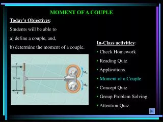
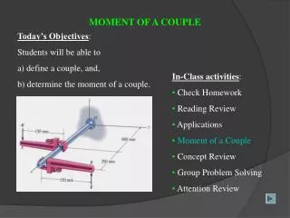
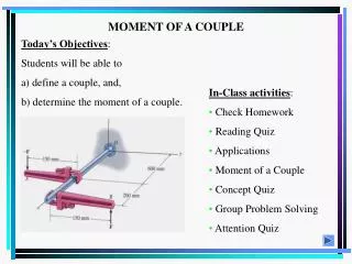
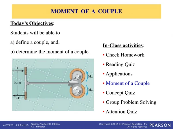
Students will be able to a) define a couple, and, b) determine the moment of a couple. MOMENT OF A COUPLE
Couples A couple is defined as two parallel forces with the same magnitude but opposite in direction separated by a perpendicular distance d.Couples are commonly applied as in the illustration below. A torque or moment of 12 N·m is required to rotate the wheel. Why does one of the two grips of the wheel above require less force to rotate the wheel?
Couples - Applications When you grip a vehicle’s steering wheel with both hands, a couple moment is applied to the wheel. Would older vehicles without power steering have larger or smaller steering wheels?
MOMENT OF A COUPLE A couple is defined as two parallel forces with the same magnitude but opposite in direction separated by a perpendicular distance d. The moment of a couple is defined as MO = F d (using a scalar analysis) or as MO = r F(using a vector analysis). Here r is any position vector from the line of action of –Fto the line of action ofF.
MOMENT OF A COUPLE (continued) The net external effect of a couple is that the net force equals zero and the magnitude of the net moment equals F*d. Since the moment of a couple depends only on the distance between the forces, the moment of a couple is a free vector. It can be moved anywhere on the body and have the same external effect on the body. Moments due to couples can be added together using the same rules as adding any vectors.
EXAMPLE - Couples 10 lb A D 3' C B 4' 10 lb • Calculate the moments about points A, B, C, and D generated by the two forces shown below by calculating the moment due to each force separately. • Then treat the two forces as a couple and calculate the moment. • Draw the object with the forces replaced by a couple shown as a free vector. Key Point: Moments due to couples are free vectors and are independent of any point.
EXAMPLE (Couples) – Scalar Approach Two couples act on the support shown. 1) Resolve the forces into x and y components2) Sketch the components3) Find the total moment produced
EXAMPLE – VECTOR APPROACH Given: A 35 N force couple acting on the rod. Find: The couple moment acting on the rod in Cartesian vector notation. Plan: 1) Use M = r F to find the couple moment. 2) Set r=rABandF = {35 k} N . 3) Calculate the cross product to find M.
EXAMPLE – Continued M=rAB F i j k = N·m 0 –0.25 0.1443 0 0 35 rAB = { 0i–(0.25)j+ (0.25 tan 30°)k} m rAB= {–0.25j+ 0.1443 k} m F = {0 i+ 0 j+ 35 k} N = {(– 8.75 – 0) i– (0 – 0) j – (0 – 0) k} N·m = {– 8.75 i+ 0j+0k} N·m
Example – Couples Two couples act on the beam. The resultant couple is zero.Find the magnitudes of the forces P and F and the distance d.
Example - Couples A couple consisting of two 15N is applied to the pipe assembly shown. Determine the moment produced by the couple. Hint: Use a cross product.
FORCE AND COUPLE SYSTEMS What are the resultant effects on the person’s hand when the force is applied in these four different ways? Why is understanding these difference important when designing various load-bearing structures?