Download
1 / 31
310 likes | 496 Views
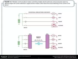
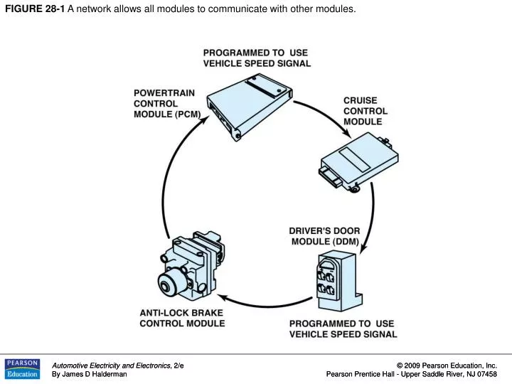
FIGURE 28-1 A network allows all modules to communicate with other modules. FIGURE 28-2 A ring link network reduces the number of wires it takes to interconnect all of the modules. FIGURE 28-3 A star link network connects all of the modules together using splice packs.

E N D
FIGURE 28-1 A network allows all modules to communicate with other modules.
FIGURE 28-2 A ring link network reduces the number of wires it takes to interconnect all of the modules.
FIGURE 28-3 A star link network connects all of the modules together using splice packs.
FIGURE 28-4 A typical BUS system showing module CAN communications and twisted pairs of wire.
FIGURE 28-5 UART serial data master control module is connected to the data link connector at pin 9.
FIGURE 28-6 The E & C serial data is connected to the data link connector (DLC) at pin 14.
FIGURE 28-7 Class 2 serial data communication is accessible at the data link connector (DLC) at pin 2.
FIGURE 28-8 Keyword 82 operates at a rate of 8,192 bps, similar to UART, and keyword 2000 operates at a baud rate of 10,400 bps (the same as Class 2 communicator).
FIGURE 28-10 A twisted pair is used by several different network communications protocols to reduce interference that can be induced in the wiring from nearby electromagnetic sources.
FIGURE 28-11 A CANDi module will flash the green LED rapidly if communication is detected.
FIGURE 28-12 A Ford OBD-I diagnostic link connector. If this had SCP communications, there would be terminals in cavities 1 (upper left) and 3 (lower left).
FIGURE 28-13 Notice that the SCP BUS connector to the OBD-I diagnostic connector is at terminals 1 and 3.
FIGURE 28-14 Start the diagnosis by using a scan tool and check to see if communications can be established with modules.
FIGURE 28-15 If there is no communication, check to see if there is a positive voltage signal on the positive side of the BUS and a negative voltage signal on the negative side of the BUS.
FIGURE 28-16 The PCM and scan tool communicate through terminal 2 (SCI transmit) and terminal 5 (SCI receive) to a scan tool at the OBD-I DLC connector.
FIGURE 28-17 CCD signals are labeled plus and minus and use a twisted pair of wires. Notice that terminals 3 and 11 of the data link connector are used to access the CLC BUS from a scan tool. Pin 4 is used to supply 12 volts to the scan tool.
FIGURE 28-18 The differential voltage for the CCD BUS is created by using resistors in a module.
FIGURE 28-19 Many Chrysler vehicles use both SCI and CCD for module communication.
FIGURE 28-20 A break-out box (BOB) used to access the BUS terminals while using a scan tool to activate the modules. This break-out box is equipped with LEDs that light when circuits are active.
FIGURE 28-21 The pin in terminal 6 is used for high-speed CAN+ and terminal 11 is used for high-speed CAN communications to a scan tool.
FIGURE 28-22 A typical 38-cavity diagnostic connector as found on many BMW and Mercedes vehicles under the hood. The use of a break-out box (BOB) connected to this connector can often be used to gain access to module BUS information.
FIGURE 28-23 A DLC from a pre-CAN Acura. It shows terminals in cavities 4, 5 (grounds), 7, 10, 14, and 16 (B+).
FIGURE 28-24 A Honda scan display showing a B and two U codes, which all indicate a BUS-related problem(s).
FIGURE 28-25 A typical (generic) system showing how the CAN BUS is connected to various electrical accessories and systems in the vehicle.
FIGURE 28-26 This Honda scan tool allows the technician to turn on individual lights and operate individual power windows and other accessories that are connected to the BUS system.
FIGURE 28-27 Class 2 serial data as viewed on a DSO with the key on. Communications is occurring because the signal voltage is changing. If there was a fault, the voltage level would likely be zero (open or short-to- ground data line) or high all of the time (shorted-to-voltage).
FIGURE 28-28 Checking the terminating resistors using an ohmmeter at the DLC.
FIGURE 28-29 Use front-probe terminals to access the data link connector. Always follow the specified back-probe and front-probe procedures as found in service information.
FIGURE 28-30 Sixteen-pin OBD-II DLC with terminals identified. Scan tools use the power pin (16) and ground pin (4) for power so that a separate cigarette lighter plug is not necessary on OBD-II vehicles.
FIGURE 28-31 This schematic of a Chevrolet Equinox shows that the vehicle uses a GMLAN BUS (DLC pins 6 and 14), plus a Class 2 (pin2) and UART.