Download
1 / 36
360 likes | 430 Views
CAD Review. A solid modeling example January 24, 2001. The example you will do is partially derived from “Parametric Modeling with Mechanical Desktop 4” by Randy H. Shih, SDC Publications, 2000, Chapter 8.

E N D
CAD Review A solid modeling example January 24, 2001 ME 386
The example you will do is partially derived from “Parametric Modeling with Mechanical Desktop 4” by Randy H. Shih, SDC Publications, 2000, Chapter 8. Though Shih emphasizes parametric modeling in the tutorial, you really don’t need all the constraints in order to complete the first assignment. So I have created a brief summary/tutorial of what you need to do to create the part. Start AutoCad with Mechanical Desktop 4 (MDT4). Accept defaults on startup of AutoCad with MDT4. Use inches. ME 386
By the way: When you need a toolbar (TB), go to here and find it. ME 386
Create some default, orthogonal work planes. Click at the center of the UCS, or simply hit ENTER. Switch to a left front isometric view (many ways to do this). ME 386
Select the XZ work plane as the current sketch plane. ME 386
The “barrel icon” indicates you have a choice of orientations or selections. Here, you could orient the new XY sketch plane in several directions with successive left-clicks. Accept the one you want with a Rt-click. ME 386
Then make invisible the three work planes (rt-click in model browser on each work plane). Orient your view to the sketch plane view… ME 386
FOR THIS EXAMPLE ONLY: Make a 2.0 wide by 1.5 high rectangle, with the lower left corner at the origin. Make a circle with the center at the origin and 2.0 radius. Trim the circle and the rectangle, such that you eliminate the right vertical side of the rectangle (see below). :EXPLODE the rectangle portion that’s left (trust me on this). Fillet the upper right corner with a 0.25 radius. ME 386
Creating a “profile” is largely associated with parametric modeling (not required for this particular assignment). However, AutoCad usually requires a profile before you can do surface and solid modeling (which is required for this assignment). So, we make a profile. Select all the sketch elements created thus far and “Enter.” Ignore the “…requiring 5 dimensions or constraints…” message. Note how your model browser has a “Profile1” now. ME 386
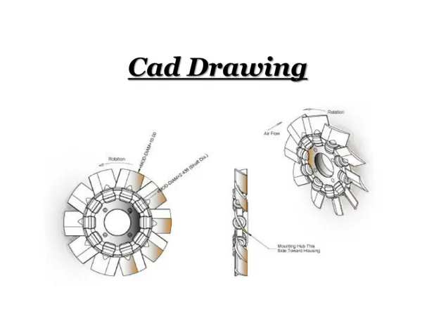
Revolve the profile. Select the vertical line of the profile. Set Revolve dialog box to below. Select OK. Look at it from isometric angles as desired. ME 386
Make work plane 3 visible (rt-click on it in browser), and be in an isometric view (left front preferred). Make the work plane 3 the new sketch plane, with the coordinate system oriented as shown below. ME 386
Switch to the sketch plane view. Create a new sketch as dimensioned to right (these dimensions are for convenience—they won’t show up in your sketch). Once done, create a profile of the closed path. Go to left front iso view for a better look. ME 386
Use the extrude command to extrude the new profile up, using settings below to join the handle to the body. ME 386
Next, we will sweep a profile to form the air tunnel. Create a line from the sketch plane center (this happens to also be workpoint1). This line is 5.5 inches long, in the negative X direction. The 5.5 inch line is now to be defined as a “2D Path.” Choose the 2D path icon, then select the endpoint away from the origin as the starting point. Elect not to create a new work plane (though it’s easier) – I’ll show how to do it manually for this exercise. ME 386
We next are going to create a new work plane, parallel to work plane 1 and at the end of the path line. Start by selecting the Work Plane icon in the Part Modeling TB. ME 386
Set up the Work Plane dialog box as shown. Note the offset (you could create this work plane in several ways). ME 386
FLIP the orientation (with lft-clicks) to match the image below. You then need to use lft-clicks to align the work plane’s UCS. If you make an error, you can always “undo” and try again. ME 386
You now have a work plane 4 in the browser. Use the New Sketch Plan icon to make work plane 4 the sketch plane. Line up the sketch plane UCS correctly, so that Y is pointing up (not technically required, but helpful). Then create a .75 radius arc on the path line, with the bottom arc end on the line. Connect the arc ends to close it. Create a profile of this arc and bottom piece. This action should create profile 3. ME 386
Sweep the Profile 3 along the 2D path, joining it to the main body. ME 386
3D fillets are easy. Do the following constant radius, 0.25 radiusfillets: • The swept tube/body intersection. • The handle/body intersection. • The top edges of handle. ME 386
Note that we still have a solid block of a part. However, plastic parts are usually in the form of constant-thickness shells. There is a neat command just for that purpose. The Shell command will shell the entire block, making it hollow, unless we tell it to “exclude” some surfaces for reference. We will exclude the end of the swept tube and the bottom surface of the entire model (flush with work plane 3). You need to lft-click with the rotating barrel to get what you want, and you need to “add” the two surfaces separately, each with rt-clicks. Then the dialog box pops up again and you click on OK. Try practicing this procedure, excluding several different surface alternatives. ME 386
Bottom surface or edge. ME 386
End surface or edge. ME 386
One last thing: A feature array. Let’s put in some vent holes. Create a new sketch plane by simply selecting the top face (after selecting the “new sketch plane” icon). It will seem as though it is at the bottom of the part, though. Don’t worry about it. ME 386
Go the the sketch plane view. Create a vent hole, offset from the center (work point 1). Note that the two lines are tangent to the arcs. Go to the left front iso view. Note that our hole is at the bottom of the part, but that’s o.k. ME 386
Make the hole outline a profile. Poof! The hole profile now sits on the top surface of the body (where we defined the sketch plane in the first place). Extrude (and cut) this hole out of the body. ME 386
Now repeat (array) the hole feature about the center of the body. Use the “Polar” option. Select the hole feature when prompted. When asked for a center of the array, select the work point 1 (if the point isn’t visible, you should make it so). ME 386
Ta-da! ME 386
A shaded view; use iso view or dynamically view, to insure that it was actually cut through the top. ME 386