Download
1 / 17
180 likes | 339 Views
F.E.T.S. RFQ Mechanical Design by Peter Savage 7 th January 2010. Ion Source. Diagnostics. Chopper. R.F.Q. L.E.B.T. FETS RFQ Mechanical Design. Goal Tuners Vacuum port design RFQ cooling Major to Minor Vane Joining Coupling in RF power RFQ section end design Support structure.

E N D
F.E.T.S. RFQ Mechanical Design by Peter Savage 7th January 2010
Ion Source Diagnostics Chopper R.F.Q. L.E.B.T. FETS RFQ Mechanical Design Goal Tuners Vacuum port design RFQ cooling Major to Minor Vane Joining Coupling in RF power RFQ section end design Support structure
The 324MHz FETS RFQ The goal is to build a Radio Frequency Quadrupole (RFQ) that will accept the 65 keV H- beam as it exits the LEBT and to accelerate the beam to an energy of 3 MeV without significant particle losses. To achieve this the RFQ must be built to tight tolerances and must operate at the design frequency of 324MHz. Temperature gradients due to localised concentrations of RF power will shift the frequency away from 324MHz. For this reason the RFQ must be adequately and evenly cooled, must be tuneable and must be assembled such that a high Q value is obtained.
FETS RFQ Mechanical Design Goal Tuners Vacuum port design RFQ cooling Major to Minor Vane Joining Coupling in RF power RFQ section end design Support structure
Tuners 2 of each type tuner prototypes have been manufactured. The next step is to test them for vacuum leaks. Total of 60 static plug tuners and 4 dynamic plug tuners. The dynamic tuners move using an off the shelf stepper motor drive. The stepper motor direction and number of turns are controlled by a feedback signal from the RF input. The dynamic tuning system is being developed by Saad Alsari.
FETS RFQ Mechanical Design Goal Tuners Vacuum port design RFQ cooling Major to Minor Vane Joining Coupling in RF power RFQ section end design Support structure
RFQ Cooling A sliced view of the CAD model showing one quarter of a 1m RFQ section. Pockets are milled deep into the copper to create a channel for chilled water to flow close to the vane tips. The channel is closed by a plate that has a baffle on the underside. Holes drilled transversally through the webs of the vacuum port provide cooling in this region. Early thermal calculations by Scott Lawrie show that the overall cooling performance is sufficient but that localised heating at the base of the vane cutback should be reduced.
FETS RFQ Mechanical Design Goal Tuners Vacuum port design RFQ cooling Major to Minor Vane Joining Coupling in RF power RFQ section end design Support structure
Methods under investigation: • Electron beam welding • High Q, medium cost, medium risk, high strength • Weld depth up to 100mm in Cu • Weld from outside – accurate depth • Small heat affected zone • Non-vacuum type available • Meeting with TWI this month • Laser welding • Medium Q, high cost, low risk, low strength • Small penetration depth • Reflectivity + thermal conductivity • Weld from inside • Access for head + offset from weld + camera • Custom head build = £100K to £300K • Vacuum brazing • High Q, medium cost, high risk, high strength • Proven technology? • Joint over entire surface by capillary action • Heat whole RFQ = distortion • All features brazed in 1 to 3 passes • Bolting + helicoflex • Low Q, low cost, low risk, medium strength • Accessible / Maintainable / Adjustable • Vacuum / RF leak risk with time • Plating • High Q?, medium cost, low risk, medium strength? • Chemicals used • Small unpredictable dimension change to outer Major to Minor Vane Joining
FETS RFQ Mechanical Design Goal Tuners Vacuum port design RFQ cooling Major to Minor Vane Joining Coupling in RF power RFQ section end design Support structure
Coupling in RF power RF power that is generated by the Klystron in R8 will be transported along waveguide and then through coax cable and into the coupler. The coupler connects to the coax via a ceramic vacuum window and terminates with a water cooled copper loop. The coupler shown here is from the ISIS 202.5MHz RFQ. Due to the reliable performance of this design the plan is build a scaled version of this one to suit our frequency of 324MHz. The ISIS coupler
FETS RFQ Mechanical Design Goal Tuners Vacuum port design RFQ cooling Major to Minor Vane Joining Coupling in RF power RFQ section end design Support structure
RFQ End Section Design • The RFQ is an assembly of 4 sections that are joined together with a vacuum and RF joint. • To ensure that the particles are not affected by the joints the vanes must maintain good alignment. • The design of the RFQ ends has a large effect on the RFQ frequency. • We plan to: • Build a CAD model of the full RFQ with 2 end flanges • Measure the eigenmodes using Microwave Studio • Measure the eigenmodes using COMSOL • Compare (and assuming agreement).... • Continue in COMSOL to measure field flatness • Modify end flange design until they exert no influence on the field flatness • Scale RFQ transversally (if required) to give 324MHz.
FETS RFQ Mechanical Design Goal Tuners Vacuum port design RFQ cooling Major to Minor Vane Joining Coupling in RF power RFQ section end design Support structure
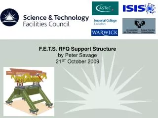
The RFQ Support Structure • Main features: • Individual structures for each RFQ section • Support to withstand 300kg load + vibration • Slide and lock positioning longitudinally on the FETS • Kinematic assembly to enable alignment between RFQ sections and relative to beamline • Act as a lifting cradle • Not obstruct fitting of numerous ancilliary components • Designed to be built within budget • Where are we now? • Design is complete • Drawings sent out for quote late December 2009 • Quotes expected by mid January 2010 • Aim is to build and invoice this financial year. • Remaining +200 parts being made now in HEP workshop
THANK YOU Any questions?