Download

1 / 23
230 likes | 330 Views
SBS-922 Membrane Proteins. Mitochondria and respiratory chains. John F. Allen School of Biological and Chemical Sciences, Queen Mary, University of London. http://jfa.bio.qmul.ac.uk/lectures. School of Biological and Chemical Sciences Seminars 2006-07

E N D
SBS-922 Membrane Proteins Mitochondria and respiratory chains John F. Allen School of Biological and Chemical Sciences, Queen Mary, University of London
School of Biological and Chemical Sciences Seminars 2006-07 WEDNESDAYS AT 12 NOON IN LECTURE THEATRE G23, FOGG BUILDING, SCHOOL OF BIOLOGICAL AND CHEMICAL SCIENCES
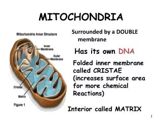
The Respiratory Chain Includes Three Large Enzyme Complexes Embedded in the Inner Membrane Molecular Biology of the Cell Bruce Alberts, Alexander Johnson, Julian Lewis, Martin Raff, Keith Roberts, and Peter Walter. 2002
1. The NADH dehydrogenase complex (generally known as complex I) is the largest of the respiratory enzyme complexes, containing more than 40 polypeptide chains. It accepts electrons from NADH and passes them through a flavin and at least seven iron-sulfur centers to ubiquinone. Ubiquinone then transfers its electrons to a second respiratory enzyme complex, the cytochrome b-c1 complex. Molecular Biology of the Cell Bruce Alberts, Alexander Johnson, Julian Lewis, Martin Raff, Keith Roberts, and Peter Walter. 2002
Fig. 1. Architecture of the hydrophilic domain of T. thermophilus complex I. (A) Side view, with the membrane arm likely to be beneath and extending to the right, in the direction of helix H1. Each subunit is colored differently; FMN is shown as magenta spheres, metal sites as red spheres for Fe atoms and yellow spheres for S atoms. A possible quinone-binding site (Q) is indicated by an arrow. (B) Arrangement of redox centers. The overall orientation is similar to that in (A), tilted to provide an improved view of the FMN and the clusters. Cluster N1a is in subunit Nqo2; N3 and FMN in Nqo1; N1b, N4, N5, and N7 in Nqo3; N6a/b in Nqo9; and N2 in Nqo6. The main pathway of electron transfer is indicated by blue arrows, and a diversion to cluster N1a by a green arrow. The distances between the centers given in angstroms were calculated both center-to-center and edge-to-edge (shown in parentheses). Clusters N3 and N4 are separated by 17.6 Å (13.8 Å edge-to-edge), and clusters N1b and N5 by 19.2 Å (16.7 Å edge-to-edge).
Fig. 2. The folds of individual subunits. Fe-S centers are shown as red spheres for Fe atoms and yellow spheres for S atoms, with cluster names in red. Subunits are not drawn to the same scale. (A) Nqo1. Its N-terminal domain is in purple, a Rossman-fold domain in blue, an ubiquitin-like domain in green, and the C-terminal helical bundle, coordinating cluster N3, in red. FMN is shown in stick representation. (B) Nqo2. The N-terminal helical bundle is shown in blue, the thioredoxin-like domain coordinating cluster N1a in green. (C) Nqo3. The N-terminal [FeFe]-hydrogenase–like domain coordinating clusters N1b, N4, and N5 is magenta, subdomains of the C-terminal molybdoenzyme-like domain are shown in I (coordinating cluster N7), blue; II, green; III, yellow; and IV, red. (D) Nqo9, coordinating clusters N6a and N6b, is shown in rainbow representation, colored blue to red from N to C terminus. (E) Nqo6, coordinating cluster N2, is shown in rainbow representation, with helix H1 indicated. (F) Nqo4. The N-terminal ß domain is shown in blue, the -helical bundle in green, the extended helix H2 in yellow, and the C-terminal ß domain in orange. Clusters are shown for orientation only. (G) Nqo5. The N-terminal /ß domain interacting with Nqo4 is shown in blue, the domain interacting with Nqo9 in green, and the C-terminal loop interacting with Nqo3 in yellow. Clusters are shown for orientation only. (H) Nqo15, shown in rainbow representation. The histidines exposed inside the putative iron storage cavity are shown.
Fig. 3. The environments of the FMN-binding site and of selected Fe-S clusters. (A) The binding site for FMN and NADH, viewed from the solvent-exposed side. Residues involved in FMN binding are shown in stick representation with carbon in yellow and hydrogen bonds as dotted lines. Residues likely to be involved in NADH binding are shown in stick representation, with carbon in magenta. Prefixes to residue names indicate the subunit number. Cluster N3 is visible to the left. Subunits are colored as in Fig. 1. A A-weighted 2Fobs – Fcalc map contoured at 1 is shown around the FMN. (B) Cluster N5 and (C) cluster N2. Cluster ligands and polar residues nearby are shown. The backbones of subunits are colored as in Fig. 1. Electron density is from a A-weighted 2Fobs – Fcalc map contoured at 1. Clusters are shown as spheres of 0.3 van der Waals radius.
Fig. 4. Possible quinone- and iron-binding sites. The solvent-accessible surface area is shown, calculated with the APBS plug-in in PyMOL using a sphere of 1.4 Å radius as a probe. It is colored red for negative, white for neutral, and blue for positive surface charges. (A) Close-up of the quinone-binding site, viewed from the membrane space up toward the peripheral arm. Residues likely to interact with the quinone are shown. Prefixes before residue names indicate the subunit number. Subunits are colored as in Fig. 1. (B) Overview of the interface with the membrane domain in surface representation. The orientation is similar to that in (A). The quinone-binding site is indicated by an arrow and Q. Helix H1 and subunit names are indicated for orientation. (C) A possible iron-binding and/or iron storage site. Histidines and other polar residues lining the cavity are shown.
Hot topics http://www.scripps.edu/mem/biochem/CI/research.html Topic 1: Where are proton-translocating site(s) and quinone-binding site(s)?It is generally believed that the energy coupling site(s) in complex I is located between Center N2 (the highest mid redox potential [4Fe-4S] cluster) and electron acceptor quinone. However, the location(s) has not been identified yet. In addition, there is no consensus about the number of coupling sites in complex I. Topic 2: Can Complex I pump not only protons but also sodium ions?Recently, Steuber's group demonstrated that complex I in certain bacteria can work as a sodium pump. A question arises whether this feature is common to complex I of other sources. Topic 3: Are accessory subunits in mitochondrial complex I really accessory?Weiss'group and Walker's group reported that acyl carrier protein of the bacterial fatty acid synthesis system is a subunit of complex I. Hatefi's group and Schulte's group showed that the HP39k subunit binds NADPH. Papa's group reported that the IP18k subunit is phosphorylated and this phosphorylation is involved in regulation of complex I activity. Videira's group suggested involvement of some subunits in the assembly of N. crassa complex I. Recently, Scheffler's group demonstrated that the MWFE subunit is essential for complex I activity. These results raise a question as to whether "the accessory subunits" are really accessory.
The Respiratory Chain Includes Three Large Enzyme Complexes Embedded in the Inner Membrane Molecular Biology of the Cell Bruce Alberts, Alexander Johnson, Julian Lewis, Martin Raff, Keith Roberts, and Peter Walter. 2002