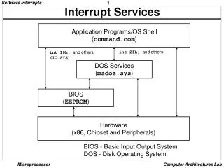
Download
1 / 59
970 likes | 2.32k Views
Interrupt in Sandy Bridge and x86 platform Taeweon Suh. July 11, 2007. Goal. Introduce the interrupt traffic via IDI in Sandy Bridge Introduce the interrupt mechanism in x86, and associate it with Sandy Bridge References The Unabridged Pentium 4 from Mindshare Inc. (P4 book)

E N D
Interrupt in Sandy Bridge and x86 platformTaeweon Suh July 11, 2007
Goal • Introduce the interrupt traffic via IDI in Sandy Bridge • Introduce the interrupt mechanism in x86, and associate it with Sandy Bridge References • The Unabridged Pentium 4 from Mindshare Inc. (P4 book) • ICH8, ICH9 CSpecs • ICH9 BIOS Specification • IA-32 Intel Architecture Software Developer’s Manual: Volume 3A • xAPIC External Architecture Specification • NHM xAPIC HAS • ISA System Architecture from Mindshare Inc. (for 8259) Here, only essential points are presented • Details are too verbose to present here • More importantly, I don’t remember everything! • Please refer to the appropriate documents (or ask questions to me, I’ll figure it out later if I don’t remember it)
Agenda • Sandy Bridge Interrupt-related IDI traffic • Local APIC in CPU (based on P4 book) • IO APIC in ICH (mostly based on ICH9 and P4 book) • 8259A • IO APIC in Tylersburg (IOH) • Interaction between Local APIC and IO APIC (based on P4 book)
PCI device How Interrupt works in x86? Sandy Bridge GSR GSR GSR GSR GT Local xAPIC Local xAPIC Local xAPIC Local xAPIC IDI IntPhy IntA 2 3 Cbo Cbo Cbo Cbo Cbo System Agent EOI 5 • Device generates an interrupt • IO APIC (or 8259) sends an MSI message (or interrupt signal) to Local xAPIC in CPU • Local xAPIC gets a vector by one of the following ways • Vector is included in the interrupt message • CPU sends IntA (interrupt Ack) to get a vector if the delivery mode was “ExtInt” in Step 2 • After getting a vector, CPU jumps to ISR (Interrupt Service Routine) based on IDT (Interrupt Description Table) • Before exiting ISR, CPU informs EOI by one of the 2 ways • CPU writes to the EOI register in Local xAPIC • Local xAPIC then sends an EOI message to IO APIC if it was a level-sensitive interrupt • CPU executes an I/O write to OCW2 if 8259 sent the vector in step 3 • CPU executes the IRET instruction DMI PCH (or ICH9) IO APIC 1 8259A
Sandy Bridge • 4+1 configuration GSR GSR GSR GSR GT IDI Uncore DDR3 Cbo Cbo Cbo Cbo Cbo System Agent CoreBo CoreBo CoreBo CoreBo CoreBo terminator RingBo RingBo RingBo RingBo RingBo PEG Ring • CacheBo • TOR • SAD • CacheBo • TOR • SAD • CacheBo • TOR • SAD • CacheBo • TOR • SAD • CacheBo • TOR • SAD PCIe DMI CV State (MESI) CV State (MESI) CV State (MESI) CV State (MESI) CV State (MESI) 2MB LLC (16 way set associative) 2MB LLC (16 way set associative) 2MB LLC (16 way set associative) 2MB LLC (16 way set associative) 2MB LLC (16 way set associative)
PCIe device Platform Picture focusing on Interrupt and Interrupt-related IDI Messages Sandy Bridge GSR GSR GSR GSR GT Local xAPIC Local xAPIC Local xAPIC Local xAPIC IDI IntLog, IntPhy, VLW IntA, EOI, RspIntAcc, FERR IntPriUp Cbo Cbo Cbo Cbo Cbo System Agent MSI IPI (Inter-Processor Interrupt) - IntLog, IntPhy DMI DMI PICe Ethernet PHY PCI-to-PCI Bridge LPC USB SATA IDE (Removed) RTC Azalia SMbus SPI 8254 Timer DMA I/O APIC GPIO LT ME PM (Power Management) Virtual INTx# PCH (ICH9 ?) SERIRQ IO APIC PIRQ[A:D]# (PCI interrupt Request) 8259A PIRQ[E:H]# (PCI Interrupt Request)
Sandy Bridge IDI Interrupt Traffic • U2C IDI commands • Source: Local xAPIC or IO APIC • Destination: Local xAPIC • Messages • IntLog: Logically addressed interrupt message – IDI APIC Write (Response: RspIntAcc) • IntPhy: Physically addressed interrupt message – IDI APIC write (Response: RspIntAcc) • VLW (Virtual Legacy Wire): A20M, INTR, SMI, INIT, NMI – IDI APIC write (Response: RspIntAcc) • LTWrite (?) – IDI APIC Write (Response: RspIntAcc) • C2U IDI commands • Source: Local xAPIC • Destination: Local APIC, IO APIC, System Agent? • Messages • IntA: Interrupt Acknowledge - IDI read (Response: GO-I) • IntPriUp: APIC priority update (TPR message) – IDI write • IntLog: Logically addressed interrupt message - IDI write (Response: GO-I) • IntPhy: Physically addressed interrupt message - IDI write (Response: GO-I) • EOI: End of level-triggered interrupt message - IDI write (Response: GO-I) • FERR: Floating point error – IDI write (Response: GO-I) • C2U IDI Response • Source: Local xAPIC • Destination: IO APIC • Message • RspIntAcc • It indicates that the interrupt request was accepted by the local xAPIC (coreBo may use it to route the message directly to the NCU)
IDI Interrupt Message Detail • IntLog: Logically addressed interrupt message • CoreReturn: This field is typically used to identify the originating APIC to implement interrupt broadcasts to all-excluding-self • Redirection Hint: • When set with logical destination mode and the lowest-priority mode, the redirection is limited to only processors that are part of the logical group of processors • Level Assert/Deassert (similar to Delivery Status bit in RT?): • Delivery status indicating the state of interrupt input (from P4) • Delivery Mode (from P4): • 000b=Fixed: Deliver the interrupt to all of the local APICs listed in the Destination field • 001b=Lowest priority: Deliver the interrupt to the processor executing the lowest-priority program • 010b=SMI • 100b=NMI • 101b=INIT • 111b=ExtInt: Delivered to the single local APIC specified in the Destination field. That processor then issues an Interrupt Ack transaction to get the vector from the 8259A INTC
IDI Interrupt Message Detail (Continued) • IntPhy: Physically addressed interrupt message • VLW (Virtual Legacy Wire): A20M, INTR, SMI, INIT, NMI
IDI Interrupts Message Detail (Continued) • IntA: Interrupt Acknowledge • Expecting the interrupt vector from 8259A • IntPriUp: APIC priority update (TPR message) • Used to update the new TPR value to the Host Bridge over the system bus (xAPIC Ext Arch Spec) for lowest priority delivery • TPR register in Local APIC (from P4) • TPR[31:8]: Reserved • TPR[7:4]: Task Priority Class • TPR[3:0]: Task Priority SubClass • EOI: End of level-triggered interrupt message
IDI Interrupt Message Detail (Continued) • FERR: Floating point error • When CR0[NE] is 1, the IDT exception vector = 10h • NE: Numeric Error Enable • When CR0[NE] is 0, the IDT interrupt vector (through IRQ13) = 75h • RspIntAcc • No specific data format in the message
P4 Interrupt Messages • Inter-Processor Messages • From Local APIC to Local APIC of one or more processors • SIPI (Startup Inter-Processor Interrupt) • Sent to the APs (Application Processors) in a MP system during the boot process. • It commands each of them to execute an initialization program that has been placed in memory by the BSP • Task Dispatch Message • OS sends it to assign a task to a processor • Interrupt Forwarding • A processor’s Local APIC may receive an interrupt and dispatch it to another processor core • Interrupt messages originated by device adapters • Assertion of an IRQ to IO APIC in the chipset. Upon detecting of the IRQ, the IO APIC formulates an interrupt message and sends it to one or more processor for handling • The MSI (Message Signaled Interrupt) takes the form of memory write. The chipset (MCH) receives the MMIO write and forwards it to processor • Interrupt messages originated by the chipset • SMI, INIT, NMI
Concerning PCIe Device Interrupts • There are 2 mechanisms to route interrupt to CPU • Direct delivery to CPU using MSI • BIOS or OS (mostly like the OS) can program an adapter’s MSI Address register with the address of the Local APICs within the processors • When the adapter issues a request by performing a memory write to this address, it is ignored by the IO APIC (because it is not being addressed) • Using IO APIC for delivery • An adapter’s MSI registers could be programmed to write an IO APIC input number (i.e., an IRQ pin number) • IO APIC would then use the RT register associated with that input number to create an interrupt message to send to processors • We are talking about this mechanism in this presentation • The PCIe spec only supports edge-triggered interrupts
NCU in Sandy Bridge • NCU handles interrupt messages of several types • MSI • Directed MSI: The destination is specified in the address fields of the MSI. The directed MSI may have a single target or multiple targets • Lowest Priority MSI: The NCU selects one of the possible destinations and converts it to a Directed MSI • IPI: It is not translated and may be only directed (no Lowest Priority supported). IPIs may have a single target or multiple targets • When CPU (if sleeping) wakes up, the Ucode will write to the filter mechanism in NCU to indicate that CPU is ready to receive interrupts • Arbitration • MSI and VLW are sent in order (as a single stream) • IPI may be sent in any order, with round robin priority among pending IPIs • VLW • Handled as broadcast to all cores (how about MSI and IPI? Is it broadcast too ?) • NCU does not filter VLW • CPU core (not NCU) has a VLW Capability Register • Core emumeration • NCU has NCU_EVENT_CORE_MASK register where PCU set it • If a bit is clear, NCU does not send messages to the corresponding core
NCU in Sandy Bridge (Continued) • The interrupt filter logic in NCU filters out interrupt messages to the sleeping cores that are not the target of the interrupt messages • The filter holds the information on the power state of all cores • It prevents unnecessary wakeups of cores in a C3 or C6 state • If a sleeping core (C3 or C6) is the target, it generates a wakeup request to it • Registers to determine the interrupt’s targeted core • These registers are updated using the “IntPrioUpd” message • The filter holds the following information globally for all cores • DFR (Destination Format Register): Logical Flat or Cluster? • Extented/Legacy APIC 1-bit • The filter holds the following information for EACH logical processor (thread) • Enable bit • APIC_ID 16-bits • LDR (Logical Destination Register) 32-bits
P4 interrupt • Memory address range associated with the Local APIC’s register set was fixed • Base address of the 4KB range was fixed at 0xFEE00000h and permits the programmer to specify (APIC_BASE[35:12] in APIC_Base_MSR) the register set’s base address starting on any 4KB-aligned address • From Pentium-4, xAPIC is used as the name. xAPIC extends the local APIC ID to 8 bits to identify 0-255 processors in the system • Interrupted messages take the form of a memory write transaction performed on the FSB • Local APIC can be disabled by setting APIC global enable/disable bit in the IA32_APIC_BASE register • Then all hardware interrupts are delivered to the processor via LINT0 (INTR) and LINT1 (NMI) input pins • Then processor is incapable of sending or receiving interrupt messages • Then processor can only receive an INIT via its INIT# input pin
Local APIC’s Register Set (P4) • The register set occupies a 4KB memory address range starting from FEE0 0000h • FEE0 0020h: Local APIC ID register: 32-bit RW • FEE0 0030h: Local APIC version register: 32-bit RO • FEE0 0080h: Task Priority Register (TPR): 32-bit RW // 0: allow all interrupts, 15: prevents all interrupts except NMI, SMI, INIT, ExtINT, INIT-deassert, and SIPI • FEE0 0090h: Arbitration Priority Register (APR): 32-bit RO // Eliminated from P4 • FEE0 00A0h: Processor Priority Register (PPR): 32-bit RO • FEE0 00B0h: EOI register: 32-bit WO • FEE0 00D0h: Logical Destination Register (LDR): 32-bit RW • FEE0 00E0h: Destination Format Register (DFR): 32-bit • FEE0 00F0h: Spurious Interrupt Vector Register: 32-bit • FEE0 0100h: In-Service Register (ISR): 256-bit RO • FEE0 0180h: Trigger Mode Register (TMR): 256-bit RO • FEE0 0200h: Interrupt Request Register (IRR): 256-bit RO • FEE0 0280h: Error Status Register (ESR): 32-bit RO • FEE0 0300h: Interrupt Command Register (ICR): 32-bit RW • FEE0 0310h: Interrupt Command Register (ICR): 32-bit RW • Local Vector Table Entries • FEE0 0320h: LVT Timer Register: RW • FEE0 0330h: LVT Thermal Sensor Register: 32-bit RW • FEE0 0340h: LVT Performance Monitoring Counters Register: 32-bit RW • FEE0 0350h: LVT LINT0 Register: 32-bit RW • FEE0 0360h: LVT LINT1 Register: 32-bit RW • FEE0 0370h: LVT Error Register: 32-bit RW • FEE0 0380h: Initial Count Register (for Timer): 32-bit RW • FEE0 0390h: Current Count Register (for Timer): 32-bit RO • FEE0 03E0h: Divide Configuration Register (for Timer): 32-bit RW
Interrupt Messages by Local APIC (P4) • IPI Message is sent by writing to the local APIC’s ICR (Interrupt Command Register) • ICR: 64-bit register (FEE0 0300h, FEE0 0310h) • Destination Field [63:56] • Destination Shorthand [19:18] • 00: No shorthand • 01: Self • 10: All including Self • 11: All excluding Self • Trigger Mode [15]: no meaning in ICR • 0: Edge • 1: Level • Level [14]: no meaning in ICR • For the INIT level de-assert delivery mode, this flag is 0. For all others, 1 • Delivery Status [12] • 0: Idle • 1: Send Pending -> Interrupt has been detected, however, it has not been posted. This bit will be cleared when the interrupt has been transmitted • Destination Mode [11] • 0: Physical • 1: Logical • Delivery Mode [10:8] • 000: Fixed -> deliver to the destination processor • 001: Lowest Priority -> same as Fixed, except interrupt is delivered to the processor executing the lowest priority task • 010: SMI • 100: NMI • 101: INIT • 110: Start Up • Vector
APIC ID and Destination Mode (P4) • Local APIC registers for destination determination • Physical ID of Local APIC • FFE0 0020h: Local APIC ID Register [31:24] • Logical ID of Local APIC • FEE0 00D0h: Logical Destination Register (LDR) [31:24] • FEE0 00E0h: Destination Format Register (DFR) [31:28] • Flat model (1111b) or Cluster Model (0000b) • Destination mode • Physical destination mode • Interrupt is accepted either by only the processor whose Local APIC has a Physical ID match on the APIC ID specified in the ICR’s Destination field [63:56] or all processors (ID of all ones) • ICR[63:56] = MDA (Message Destination Address) • Logical destination mode • Interrupt is accepted by all of the processors whose Local APICs belong to the targeted group • MDA in the message is compared against LDR and DFR • Flat Model: each of 8 bits in MDA acts as a selector. For example, 10110011b selects Local APICs 0,1,4,5, and 7, and contents of Local APIC 5’ LDR should be 00100000b to be selected -> Max 8 Local APIC units • Cluster Model: Flat cluster, Hierarchical Cluster Flat cluster: MDA[31:28] contains the target cluster ID, MDA[27:24] are used to select up to 4 Local APICs within the cluster
How Local APIC knows which messages to accept on FSB? • Address FEEx xxxxh on FSB is for Local APIC • Address format (Interrupt message) on FSB • FEEx x00yh • [63:32]: 0s • [32:20]: Must be FFEh • [19:12]: Destination ID (xx specifies an APIC ID) • [11:4]: Reserved • [3]: Redirection Hint • [2]: Destination Mode (Physical or Logical) • [1:0]: Must be 00b • Data format on FSB • [31:16]: Must be 0000h • [15]: Trigger Mode • [14]: Delivery Status • [13:12]: Must be 00b • [11]: Destination Mode • [10:8]: Delivery Mode (Fixed, Lowest-Priority, SMI, NMI, INIT, ExtInt) • [7:0]: Vector
Interrupt Priority (P4) • Interrupts (Priority Class 0: vector number 0~15) have higher priority than interrupt vectors (16~225) (xAPIC Ext Arch Spec) • But Class 15 has the highest among class 1-15 • Eligibility test for user-defined interrupt (vectors from 32d to 255d) • To be considered for dispatch to the processor core, the interrupt’s class much meet or beat the value in the PPR (Processor Priority Register) • PPR is set to whichever is bigger between TPR (OS sets it) and class of in-service interrupt
Misc • ExtINT and Non-Vectored interrupts (I think, NMI, SMI, INIT, A20M) bypass the IRR/ISR registers in Local APIC and signaled directly to the processor core
IO APIC in ICH9 • IO APIC • There are 24 IRQ inputs • For each of the IRQ inputs, the IO APIC implements a register of which set is called RT (Redirection Table)
IO APIC Register Set (ICH5, ICH9) • IO APIC register set base address: FEC0 000h (ICH5) • To reprogram, APICBASE register is provided • Register set • FEC0 x000h: Index register: 8-bit RW • FEC0 x010h: Window (data) register: 32-bit RW • FEC0 0020h: IRQ assertion register: 32-bit WO (Is it obsolete in ICH9?) • Device adapter performs an MSI write to deliver an interrupt request to the IO APIC (in the form of a virtual IRQ pin assertion) • Device adapter writes a 32-bit value into this register. Bit [4:0] contain the IRQ number, but only valid values are 0-23 • ICH5 specifies that the selected IRQ pin’s RT register must be programmed as an edge-triggered interrupt • FEC0 x040h: EOI register: 32-bit WO – only [7:0] is used for vector • Indirectly-Accessed Registers • Index 00h: Identification register: 32-bit RW • Index 01h: Version register: 32-bit RO • Index 10h-11h: Redirection Table Register 0 (associated with IRQ0) • Index 12h-13h: Redirection Table Register 1 (associated with IRQ1) • …. • Index 3Eh-3Fh: Redirection Table Register 23
IO APIC Redirection Table Register (ICH9) • 64-bit RT entry format • [63:56]: Destination • [16]: Mask • 0: Unmasked • 1: Masked: Interrupts are neither latched nor are they delivered • [15]: Trigger Mode • 0: Edge-triggered • 1: Level-triggered • [14]: RIRR (Remote Interrupt Request Register) • This bit only applied to level-sensitive interrupts • 0: Cleared when an EOI message containing this pin’s vector has been received from a Local APIC • 1: Set when IO APIC sends the level interrupt message to the CPU • [13]: Input pin polarity • This bit only applies if this pin is defined as a level-sensitive interrupt. It specifies if a valid interrupt request is signified by an electrical low or high • 0: high • 1: low • [12]: Delivery Status • 0: idle • 1: Send Pending. (interrupt is pending, not yet delivered) The interrupt message has not yet been accepted by the Local APIC • [11]: Destination Mode • 0: Physical • 1: Logical • [10:8]: Delivery Mode (Fixed, Lowest Priority, SMI, NMI, INIT, ExtInt) • 000: Fixed • 001: Lowest-priority • 010: SMI (not supported): So how does PCH send SMI, NMI, or INIT to CPU? • 100: NMI (not supported) • 101: INIT (not supported) • 111: ExtInt • [7:0]: Vector • Valid values range between 10h and FEh • It contains the user-defined interrupt vector associated with this pin
Interrupt Delivery Order in IO APIC (P4, ICH5) • Unlike the Local APIC, the IO APIC does not implement a priority scheme to determine the order in which interrupt messages associated with each of its inputs are delivered to the processors • The IO APIC constantly rotates through its RT registers
Misc • Until RIRR is reset, IO APIC will not reissue another message regardless of the state of the input event • The Local APIC will broadcast an EOI message over the system bus to all IO APICs indicating that the level-triggered interrupt has been serviced • Broadcast EOI model allows for the capability of having multiple IO APICs assign a common interrupt vector to a RT • It is the responsibility of the system software to ensure that an interrupt vector, which is shared between multiple IO APICs is programmed with the same trigger mode • Interrupt (with delivery mode ExtINT) signaled on a local interrupt pin (LINT0, LINT1) is always treated as level-triggered • For level-triggered interrupt, EOI is sent to IO APIC • Again, ExtINT and Non-Vectored interrupts (I think, NMI, SMI, INIT, A20M) bypass the IRR/ISR registers in Local APIC and signaled directly to the processor core • My comment: Make sense because interrupt from 8259 will use ExtINT, and 8259 has its own ISR, IRR registers
Cascading 82C59As 8086 82C59A (Master) Still in ICH INTR IR0 IR1 IR2 IR3 IR4 IR5 IR6 IR7 INTR 82C59A (Slave) IR0 IR1 IR2 IR3 IR4 IR5 IR6 IR7 INTR INTA Bus cycle type decoder INTA
82C59A Registers • ICW1, ICW2, ICW3, ICW4 • Initialization Command Word • ICWs should be initialized before the normal operation • ICW registers should be accessed in a “predefined sequence” • In 8086/8088, • The master 8259 is accessed through I/O port addresses (20h, 21h) • The slave 8259 is accessed through I/O port addresses (A0h, A1h) • OCW1, OCW2, OCW3 • Operation Command Word • OCWs can be written anytime after initialization • OCW1: IMR (Interrupt Mask Register) • OCW2 • EOI (End of Interrupt) clears the highest-priority bit in ISR (In-Service Register): It is done by writing 20h to I/O port 20h or A0h • b’001 in bit7-5 (R, SL, EOI) means non-specific EOI • OCW3 • To read ISR or IRR (Interrupt Request Register)
Initialization Sequence for Master in 82C59A • Out 15h, port 20h // ICW1 write (should set bit4 to 1) • 1 in bit0 (IC4): ICW4 is needed • 0 in bit1 (SNGL): Cascade mode • 1 in bit2 (ADI): no effect in 8086/8088 • 0 in bit3 (LTIM): Edge trigger mode • Out 08h, port 21h // ICW2 write • Master 8259’s 8 inputs (IRQs) have interrupt IDs ranging from 08h to 0Fh • Out 04h, port 21h // ICW3 write • In master mode, 1 in bit2 means that IRQ2 is connected to a slave • Out 01h, port 21h // ICW4 write • 1 in bit0 (uPM): 8086/88 mode -> 8259 must send an interrupt vector to the processor in response to interrupt acknowledge • 0 in bit1 (AEOI): Normal EOI • 0x in bit3, bit2: Non-buffered mode • 0 in bit4 (SFNM): Not special fully nested mode • Out FBh, port 21h // OCW1 write: IMR (Interrupt Mask Register) • Disable all IRQ inputs except IRQ2 (requests from the slave 8259)
Initialization Sequence for Slave in 82C59A • Out 15h, port A0h // ICW1 write (should set bit4 to 1) • 1 in bit0 (IC4): ICW4 is needed • 0 in bit1 (SNGL): Cascade mode • 1 in bit2 (ADI): no effect in 8086/8088 • 0 in bit3 (LTIM): Edge trigger mode • Out 70h, port A1h // ICW2 write • Slave 8259’s 8 inputs (IRQs) have interrupt IDs ranging from 70h to 77h • Out 02h, port A1h // ICW3 write • In slave mode, bits 2-0 identify the salve. In this case, slave ID is 2 • Out 01h, port A1h // ICW4 write • 1 in bit0 (uPM): 8086/88 mode • 0 in bit1 (AEOI): Normal EOI • 0x in bit3, bit2: Non-buffered mode • 0 in bit4 (SFNM): Not special fully nested mode • Out FFh, port A1h // OCW1 write: IMR (Interrupt Mask Register) • Disable all IRQ inputs
Register Read in 82C59A • ISR, IRR read • First write either 03h (for ISR) or 02h (for IRR) to OCW3 at port 20h or A0h • RR in D1: Register Read • RIS in D0 selects whether it is ISR or IRR • Next time when the port 20h is read from, 8259 will drive data bus with ISR or IRR contents • IMR read • No need to access OCW3 • The output data bus will contain the IMR whenever RD is active and A0=1 (OCW1) – address 21h or A1h OCW3
Register Write in 82C59A • A0, and D4, D3 differentiate the target register (OCW1, OCW2, OCW3)
Interrupt Priority in 82C59A • During the POST (Power-On Self Test), both of the interrupt controllers are programmed to used a fixed priority scheme • IR0 is the highest priority and IR7 is the lowest priority • In the cascade, • Master’s IR0 is the highest • Master’s IR1 is the second highest • Master’s IR2 is connected to interrupt output of the slave 8259. So, the slave 8 inputs IR8~IR15 come next in priority
3 Schemes for Connecting INTR (8259) and NMI to Processor (xAPIC Ext Arch Spec) • Direct Connect • Local xAPIC is Disabled • INTR (8259A) is connected to LINT0 (INTR) • NMI from system board is connected to LINT1 (NMI) • INTR and NMI are connected to processor core bypassing Local xAPIC • Through Local xAPIC • Local APIC is Enabled • Connection is the same as the Direct Connect • LVT entries for LINT0 and LINT1 are programmed with ExtINT and NMI delivery modes respectively • Through IO APIC • IO APIC and Local APIC are Enabled • INTR and NMI are connected to an interrupt input mechanism of the IO APIC. RT entries are programmed with ExtINT and NMI delivery mode respectively • In the xAPIC architecture, only one IO APIC can deliver messages of type ExtINT • Local APIC signals interrupt to core bypassing ISR, IRR, and priority logic • Mixed Mode Operation? – not recommended
ICH9 PIRQ to IRQ Router and Connection (from ICH9 BIOS Spec) Target IRQ# set by BIOS ICH9 60h 9 PIRQA# PIRQB# 61h 10 8259A PIRQC# 62h 5 Interrupt to CPU IRQ PIRQD# 63h PIRQE# 68h 11 PIRQF# 69h I/O APIC PIRQG# 6Ah PIRQA# INTIN16 INTIN17 INTIN18 INTIN19 INTIN20 INTIN21 INTIN22 INTIN23 PIRQB# PIRQH# 6Bh PIRQC# D31:F0 PIRQ Routing Registers PIRQD# PIRQE# PIRQF# PIRQG# PIRQH#
ICH9 PCI Interrupt Routing Control (from ICH9 BIOS Spec) Controlled by programmable registers in Chipset config space ICH8 (?) CCR INTx Mapping (HW “Straight”) INTA#->PIRQA# INTB#->PIRQB# INTC#->PIRQC# INTD#->PIRQD# Dev31 interrupts INTx Selection (D31IP) INTA#/B#/C#/D# PIRQy Mapping (D31IR) LPCBR (D31, F0) Interrupt Router Interrupt to CPU IRQs 8259A Dev29 interrupts INTx Selection (D29IP) INTA#/B#/C#/D# PIRQy Mapping (D29IR) Dev27 interrupts INTx Selection (D27IP) INTA#/B#/C#/D# PIRQy Mapping (D27IR) PIRQA#-H# PCIe Root Ports Dev26 interrupts INTx Selection (D26IP) INTA#/B#/C#/D# PIRQy Mapping (D26IR) I/O APIC Dev25 interrupts INTx Selection (D25IP) INTA#/B#/C#/D# PIRQy Mapping (D25IR) INTA#/B#/C#/D# INTA#/B#/C#/D# INTx Mapping (HW “Swizzling”) INTx Mapping (HW “Straight”) Assert_INTx from DMI link INTA#/B#/C#/D# PIRQy Maping (Board Specific) INTx Mapping (HW “Swizzling”) Port#1: INTA#->INTA#, INTB#->INTB#, INTC#->INTC#, INTD#->INTD# Port#2: INTA#->INTB#, INTB#->INTC#, INTC#->INTD#, INTD#->INTA# Port#3: INTA#->INTC#, INTB#->INTD#, INTC#->INTA#, INTD#->INTB# Port#4: INTA#->INTD#, INTB#->INTA#, INTC#->INTB#, INTD#->INTC# PCI slots
Current Synopsys Model (ICH9) in Innovator ICH9 CCR JadeIO X86_IRQ Dev31 interrupts INTx Selection (D31IP) INTA#/B#/C#/D# PIRQy Mapping (D31IR) KBD, HPET … Dev29 interrupts INTx Selection (D29IP) INTA#/B#/C#/D# PIRQy Mapping (D29IR) APICInt16 ~ APICInt23 Dev27 interrupts INTx Selection (D27IP) INTA#/B#/C#/D# PIRQy Mapping (D27IR) Dev26 interrupts INTx Selection (D26IP) INTA#/B#/C#/D# PIRQy Mapping (D26IR) I/O APIC RCBA (Root Complex Base Address) D31, F0, 0xF0 Dev25 interrupts INTx Selection (D25IP) INTA#/B#/C#/D# PIRQy Mapping (D25IR) iMem64 LPCBR (D31,F0) Routing Control Register nPIRQA (0x60) nPIRQB (0x61) nPIRQC (0x62) nPIRQD (0x63) nPIRQE (0x68) nPIRQF (0x69) nPIRQG (0x6A) nPIRQH (0x6B) HAVC, Rubicon, Azalia IRQ3 IRQ4 IRQ5 IRQ6 IRQ7 IRQ9 IRQ10 IRQ11 IRQ12 IRQ14 IRQ15
IO xAPIC in Tylersburg (IOH) • IO xAPIC • Support for 24 unique interrupt vectors via a 24 entry-deep redirection table (RT) • Interrupts serviced are upstream INTx# virtual wire interrupts (INT[A-D]) from the PCIe ports and legacy virtual wire interrupts from the Crystal Beach3-DMA engine • If IO xAPIC is disabled (PIC mode), the behavior is like prior chipsets i.e., these interrupts are combined together to create a consolidated set of four virtual wire interrupts and then forwarded to the legacy ICH’s interrupt controller
IO APIC and Local APIC (P4) • Flow of an level-sensitive interrupt delivery • On detection of the low phase, the IO APIC sets the remote IRR and the Delivery Status bit to 1 in RT register, indicating that the message has not yet been accepted by the processors • The IO APIC formulates an interrupt message as a memory write to the Local APICs • MCH initiates a memory write on FSB • The Local APIC sets the bit in IRR (Interrupt Request Register) that is selected by the user-defined vector delivered in the message • Upon receipt of the no data response to the memory write transaction, MCH sends an acknowledgement of successful message transmission to ICH • This would be “ResIntAcc” in IDI • The IO APIC in ICH clears the Delivery Status bit in RT register to 0 • At the end, the ISR performs a memory write to the Local APIC’s EOI register. This causes the Local APIC to clear ISR (In-Service Register) bit • The Local APIC also performs a memory write transaction on the FSB to write the interrupt vector to the IO APIC’s EOI register • This would be “EOI message” in IDI • It clears the Remote IRR bit in its respective RT entry to 0, thereby re-enabling recognition of a low level interrupt
IO APIC and Local APIC (P4) (Continued) • Flow of an edge-triggered interrupt delivery • On detection of the low-to-high transition, the IO APIC sets the Delivery Status bit to 1 in RT register, indicating that the message has not yet been accepted by the processors • The IO APIC formulates an interrupt message as a memory write to the Local APICs • MCH initiates a memory write on FSB • The Local APIC sets the bit in IRR (Interrupt Request Register) that is selected by the user-defined vector delivered in the message • Upon receipt of the no data response to the memory write transaction, MCH sends an acknowledgement of successful message transmission to ICH • This would be “ResIntAcc” in IDI • The IO APIC in ICH clears the Delivery Status bit in RT register to 0 • At the end, the ISR performs a memory write to the Local APIC’s EOI register. This causes the Local APIC to clear ISR (In-Service Register) bit There is no message to clear anything in IO APIC at the end of ISR in this case!? √ Remote IRR in RT Entry only applies to level-sensitive interrupts A Write to the EOI register in Local APIC must NOT be included in the handler routine for an NMI, SMI, INIT, ExtInt or SIPI (IA-32 manual)