Download
1 / 27
270 likes | 427 Views
Gamma Cherenkov-Transition radiation of High Energy Electrons and Methods for the Measurement of the Refractive Index of MeV Photons Using Total External Reflections (or “A Problem in XXI Century Physics and Experimental Methods

E N D
Gamma Cherenkov-Transition radiation of High Energy Electrons and Methods for the Measurement of the Refractive Index of MeV Photons Using Total External Reflections (or “A Problem in XXI Century Physics and Experimental Methods for Its Solution” asit could be presented as an invited talk in August 2013 at ICNFPin Greece) K.A. Ispirian Alikhanian National Scientific Laboratory, YerPhI (Invited talk) RREPS-MEGHRI 2013
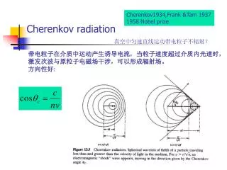
1. Introduction or Formulation of the Problem Fig.1 The behavior of the dependence of n of substances upon ћω. Using the notations .The measured values at ћω=0.78, 1.1 and 1.9 MeV areδ~10-10-10-9 in good agreement with theoretical explanation with the help of Delbruck scattering [1]. 1. D. Habs, M.M. Gunther, M. Jentschel, W. Urban, a) arXiv: 1111.3608, 2011; b) Phys. Rev. Lett, 108 (2012) 184802.
The authors of [1] has published works on possible applications [2-5] of the discovery in gamma ray optics, nuclear physics etc. They promised after a few months to obtain new results on GAMS6 and even prepared as the Snigirev X-ray lenses gold gamma lenses (see Fig.2). However, no publications confirming the results of [1] appeared in 2013. Moreover, in October 2012 a comment [6] has been sent to PRL and published in March 2013 without any answer from the authors of [1]. In [6] using the Delbruck cross sections, calculated in [1], it has been shown that one can obtain δ values only ~106 times less than those obtain theoretically and experimentally in [1]. Fig.2 Photo of Au lenses. 2. D. Habs, M.M. Gunther, M. Jentschel, P.G. Thirolf, ArXiv:1201.4466, 2012. 3. M. Jentschel, Gamma Ray Optics, http://www.inn.jir. 4. D. Habs, “Delbruck sc…appl”, www.eli-np.ro; cyclotron.tamu.edu…/presentations 5. CERN Courier, Jul.18,2012; Physics World, Science Daily, and many newspapers…. 6. J.T. Donohue, Phys. Rev. Lett. 110, 129501, 2013.
It is well known that in the regions where n>1 the charged particles with E>Ethr produce • Cherenkov radiation (CR) in radio-optical regions[7-10], • Less known X-ray Cherenkov Radiation (XCR) in X-ray region [6,7] • c) And as it has been predicted and will be discussed in this revue based on [8] Gamma ray CR (GCTR) in gamma region. • The experimental observation and the study of GCTR may confirm • or decline the results of [1] and solve the above problem. 7. Jelley, Cherenkov Radiation and Its Applications, Pergamon Press, London, 1958. 8. V.P. Zrelov, Izluchenie Vavilova-Cherenkova i Ego Primenenie M., Atomizdat, 1968. 9. P.A. Cherenkov, Dokl. Akad. Nauk SSSR, 2, 451, 1934. 10. I.M. Frank, I.E. Tamm, Dokl. Akad. Nauk SSSR, 14, 109, 1937. 11. V. A. Bazilev, N.K. Zhevago, Izluchenie Bistrikh Chastits v Veshchestve i vo Vneshnikh Polyakh, Moscow, Nauka, 1987. 12. K.A. Ispirian, Lecture “X-Ray Cherenkov Radiation”, in Proc. of NATO ARW Adv.photon Sources and Apps, NorHamberd, Armenia, 29 August-3 Sep, 2004, NATO Sc. Ser. II, Math. Phys Chem. 2005, Vol. 199, p. 217. 13.M. A. Aginian, K. A. Ispirian and M. Ispiryan, a) ArXiv:1302.5208, 2013; and To be published in b) European Physics Letters; in c) Izvestya of NAS of Armenia; in d) Proc of this Conf .
2. The 2012 Experimental and Theoretical Results of D. Habs et al [1](in brief) 2a.The Arrangement and Method The experiment has been carried out at Institut Laue-Langevin (ILL) On the facility GAMS5 [14] (see Fig. 3) Fig.3 The scheme a) and the principle of the measurement method b). 14. Doll et al, GAMS5, J. of Res. of Nat. Inst. of Stand. And Technologies, 105, 1, 2000.
2b. Experimental Results Fig.4 Deviation angle vs ћω [1] Table I [1]
2c.Theoretical Interpretation and Results of [1] Fig. 5 Cross sections of 1. Photo effect, 2. Rayleigh scattering and 3. Compton scattering, giving negative contribution into δ and 4. Pair production, 5. Corrected pair production, 6. Delbruck elastic scattering and 7. Delbruck inelastic scattering in Si, giving positive contribution into δ (see next slides).
A few words on QED non-linear process of Delbruck scattering on nucleus Coulomb field γ+Z→Z+γ It is called inelastic when the nucleus takes the recoil: it is elastic when the total crystal takes the recoil (like Mossbauer effect). Just as for Unruh effect (PRL, 2008) D. Habs and M. Gunther from LMU/MPQ have calculated σ-s (and nobody else) with the help of perturbative QED, which is understandable only for the authors. Now using these σ(ћω), optical theorem, dispersion relation , (1) (2) and the relation (3) one can calculate the contribution of any process into δ.
In [1] it is given exper. and theor. results on |δ| Fig. 6 absolute values of δ vs ћω. Besides the experimental points the curve 1 (δ<0) is for (photo+Compton effects), curve 2 (δ >0) is for (inelastic and elastic Delbruck scattering+corrected pair production) and curve 3 is for superposition of 1 and 2. Good agreement between experimental and theoretical results!
However, in [6] (DonohuePRL2013) using the formula (from Goldberger, Watson and the Delbruck elastic and inelastic cross sections calculated by D. Habs and shown in Fig. 5(curves 6 and 7) the author of [6] obtains δ≤2x10-15. Despite to [1] where it is shown that in the region ~1 MeV Delbruck contribution is ~106 times larger and results in changing the negative δ into positive. The author of [6] concludes that Delbruck can not save the results. Since the authors of [1] did not answer the comments [6] and there is no new experimental and theoretical results, further we shall consider processes which allow to solve this contradiction experimentally. (4)
3. Theoretical Predictions on GCTR Just as in the case of XTR the method of developing the theory of GCTR is the substitution of the values of χ’and χ’’ into CR or XTR formulae. The curves1 and 2 in Fig. 7 are the interpolations of the data of [1] on χ’=2 δ and using known Tables of μ . Fig.7. The dependence of χ’and χ’’ of Si upon ћω.
3.1 Estimates of GCTR Based on Frank-Tamm Theory on CR For γ>>1 substituting (χ’’=0) into the expressions for CR angle, , and spectral distribution, (for unit radiator length) , one derives , (5) , (6) (7) Artificially introducing absorption by the method of [10] one obtains ; , i.e ; . . And for which takes place for GCTR (see below) . (8) For Si radiator with at ћω=1 MeV one obtains (9) and 15. A.I.Alikhanian, F.R. Arutiunian, K.A. Ispirian, M.L. Ter-Mikaelian, Zh. Eksp. Teor. Fiz. 41 (1961) 2002.
3.2 Theory of GCTR based on Ginzburg-Frank-Garibian Theory of TR The first hints that TR formulae describe also CR have been published in 60-70-ies [16,17]. Below the results on XTR of the work [18,19] reviewed in [20,21] serve for construction of GCTR theory. 3.2a GCTR Produced at an Interface between two Media and Its Formation Length According to [21] the formation length of XTR in a medium is a complex magnitude and is given by the expression . (10) 16. G.M. Garibian, I.I. Goldman, Dokladi Akad. Nauk. Arm. SSR, 31 (1960) 219. 17. K.A. Ispirian. S.T. Kazandjian, Fizika Tverdogo Tela, 15, 1551,1973. 18. G.M. Garibian, L.G. Gevorgian, C.Yang, Zh. Eksp. Teor. Fiz. 19. X. Artru, G.B. Yodh, G. Mennessier, Phys. Rev. D12 (1975) 20. M.L. Ter-Mikaelian, The Influence of the Medium on High Energy Processes at High Energies, Publishing House of Acamemy of Science of Armenia, Yerevan, 1969; High Energy Electromagnetic Processes in Condensed Media, Wiley Interscience, New York, 1972. 21. G.M. Garibian, Yan Shi, Rentgenovskoe Perekhodnoe Izluchenie, Publishing home of Academy of Sciences of Armenia, Yerevan, Armenia, 1983.
The module of which is the distance …….will be called GCTR formation length in medium From (11) in vacuum (χ’=χ’’=0) with a maximum at equal to As it follows from (11) when GCTR takes place and in contrast to XTR Now using the formulae (1.59) of [21] for XTR in small angle and γ>>1 approximation, one obtains for GCTR produced at 1 interface. (13) One can derive (13) from formula for GCTR in a plate [6,12] An important remark on (13) that can be omitted for time . (11) (12) . .
3.2b GCTR produced in a plate With the help of the formula (2.21) of [21] or formula (3.27) of [11] for a plate one derives the following formula for the spectral-angular distribution of GCTR (14) produced in a plate (14), despite to that produced at an interface (13) and in stack of plate (see below), is of experimental interest. That is why all the below numerical results are for this case.
3.3 GCTR produced in a Stack of Plates According to [21] the spectral angular distribution of RTR, therefore, of GCTR produced in a radiator consisting of M plates with thicknesses l1 and μ1 in vacuum or air with thicknesses l2 and μ2 =0(therefore, χ2’= χ2’’is given by the formula (15) where is GCTR produced at 1 interface and given by (13) and the factors and which are due to interference in one and M plates are given by (16) (17) (18) , , ,
As the num. calculations with (15)-(18) show…explain if time is enough • 4. Numerical Results on GCTR Produced in a Plate • are for E=20 GeV and Si radiators with thickness Lrad=0.1Х0= 1cm • (otherwise the electron energy (and V) will be degradated) • 4.1 The spectral distribution of GCTR in a plate • Is shown by the curve 1 of Fig. 8. The curve 2 is the background • bremsstrahlung calculated taking into account the Ter-Mikaelian • effect [20]…It is seen that… • Fig. 8. The spectral distributions • of GCTR and bremsstrahlung. • The integrals of the curves 1 and 2 are equal to NGCTR=1.34 and • Nbr=0.1, respectively, i.e S/N~10 ….
4.2 The Angular Distribution of GCTR. • Is shown in Fig.9 • Fig. 9. The angular • distribution of GCTR • As it is seen GCTR is emitted mainly in the angular interval from 20 μrad up to 60 μrad, in agreement with the above estimates obtained with the help if Frank-Tamm theory. The integration of the curve of the Fig.9 again gives NGCTR=1.3.
4.3 The Dependence of GCTR on the Electron Energy (solid curve) as well as of bremsstrahlung (dashed curve) emitted in 760-10000 MeV region is shown in Fig. 10 Fig.10 The energy dependence of the number of the GCTR and background bremsstrahlung photons. As it is seen just as for XTR (TRD) there is a “threshold”....
4.4 The GCTR Dependence on the radiator thickness Is shown in Fig. 11. It is important for experiments on GCTR since Lrad must be < X0 in order to avoid energy degradation (for Si X0=9.6 cm), but large as it is possible to have greater NGCTR . Fi Fig.11 NGCTR vs Lrad. As it is seen approximately up to 0.1 cm, NGCTR~L2rad, after which NGCTR~Lrad. As a consequence …
4.5 Spectral Distributions of GCTR produced in Stack of Plates (can be omitted to save time) Fig. 11’ Spectral distribution of GCTR produced in stacks of plates The integrals of these curves of a), b), c) and d) give N=1.6, 0.8, 0.2 and 1.6 , respectively. The understanding and interpretation of These curves on the basis of Fig.11……
5. Experimental Possibilities As it is proposed in [6,13] one can use the experimental arrangement similar to those used at SLAC [22] and CERN SPS [23] for the study of LPM effect. The SLAC beam has the difficulty that it must contain 1 electron per short pulse, while the SPS beam being much longer, allows to detect a few GCTR photons per pulse. Fig.12 shows the proposed in this work, slightly modified arrangement of [23] which can be used for GCTR. Fig.12 The proposed experimental arrangement. 22. S. Klein, Rev. Mod. Phys. 71, 1501, 1999. 23. H.D. Hansen, U.I. Uggerhoy, C. Biino et al, Phys. Rev. D 69, 032001, 2004.
Let us note that the spectra measured at SLAC by 25 GeV electrons in (1-10) MeV region did not reveal any exceeding over the calculated spectra of bremsstrahlung calculated by various theories [22]. One cannot use this fact to decline the results of [1], because no measurements on Si have been performed. 6. Measurement of the n(ω) in MeV Region Using Total External Reflection It is well known that if n>1 (optical) it can take place total internal reflection at the boundary medium-vacuum with θcint=arcsin(1/n). Similarly, if n<1 (X-rays) it can take place total external reflection (TER) at boundary vacuum – medium with θcrTER=(2δ)1/2. TER was discovered in[24]. Important contribution in the study of TER has been carried out in [25]. 24. A.H. Compton, Philosophical Magazine, 45, 1121, 1923. 25. A.I. Alikhanov, L.A. Artsimovich, Z. Phys. 82, 489, 1933.
If δ~ 10-9, θcrTER= 45 μrad, which is not very small, nrad, as the angles in [1]. In many works of the past (see, [26]) it has been proposed, but not realized, to use TER for various purposes, in particular for the “monochromatization” of MeV photon beams. However, such MeV experiments become realistic only recently connected with the advance of the method of inverse Compton scattering intense photon sources [27,28]. The suitable and available parameters are at present the facility HiGS at Duke university, which provides 108-1010 photons per second in a ~10 % BW and soon the ELI facility in Romania, which will provide ~1013 photons per second in a ~1 % BW. 26. M.A. Kumakhov, Radiation of Channeled Particles in Crystals, Energoatomizdat, Moscow, 1986 (in Russian). 27. Y.K. Wu, Overview of present and future Compton photon sources, PAC 2012, TUXB03. 28. T. Raubenheimer, Lecture: Inverse Compton and FELs, SLAC Summer School on Electron and Photon Beams, 2013.
Of course, the intensity of the HiGS beam is much less than that of GAMS5 (~1015), but it has angular spread of θrad ~1/γ~4x10-4 rad, while the worse monochromaticy is not important for our application because n(ω) varies slowly. Now it is proposed to use TER for measuring of n(ω). Fig.13 shows the proposed setup: Fig. 13 An arrangement for the measurement of n(ω) with the help of TER (or TIR placing the reflector in the insert)
Increasing the glancing angle θgl one can expect (see review articles on TER) the following well known dependence of the rate of TER (or TIR) photon detection rate upon θgl, 1 for ideal and 2 for real beams. Fig. 14 Typical dependence rate vs θgl Such dependence allows to fix and measure the angle θcrTER when the reflected photon detector begins to detect the photons of TER with error ± Δθgl /2 . Then δ is determined from θcrTER=(2δ)1/2. To carry such measurements it is necessary to have (1-10) MeV photon beams with 1) angular spread much less than the above θcrTER~45 microrad and 2) sufficient intensity. These are provided by the fact that only a small fraction equal to F=(θacc/θrad)2 of the beam emitted under angles smaller than θacc=Tθgl /2L (T is the size of the reflector, L is the distance between the photon source and reflector) strikes the Si reflector.
The advantages of the proposed method compared with the method of [1]: 1) there is no need of monochromatic MeV photons and high detection energy resolution and 2) instead of nanoradian accuracies of [1] microradian accuracies of angles is enough. Taking T=3cm, L=10 m (see Fig. 13), one obtains for HiGS (γ=2.4x10³) one obtains F=10-8. Therefore, for HiGS one expects to detect ~1-103 TER photons per second. In the same way one can carry TIR experiment assuming n>1 Thus at present it is possible for short time to carry the proposed TER (TIR) experiments and determine δ and n for materials at HiGS. At present negotiations are going to carry out the above proposed experiments on GCTR and direct measurement of n(ω) by TER in MeV region and confirm or decline the discovery of [1]. Thank you for attention and possible criticism and help