Download
1 / 37
410 likes | 994 Views
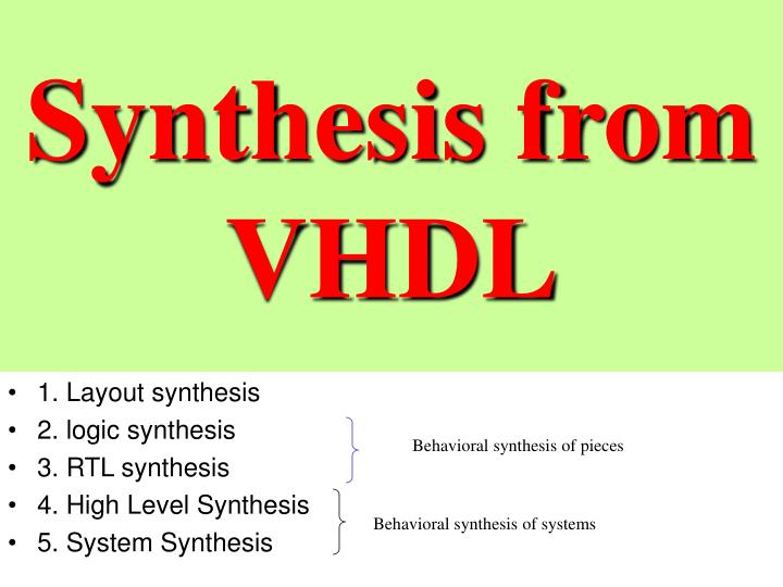
Synthesis from VHDL. 1. Layout synthesis 2. logic synthesis 3. RTL synthesis 4. High Level Synthesis 5. System Synthesis. Behavioral synthesis of pieces. Behavioral synthesis of systems. Hardware describing languages (HDL). Describe behavior not implementation

E N D
Synthesis from VHDL • 1. Layout synthesis • 2. logic synthesis • 3. RTL synthesis • 4. High Level Synthesis • 5. System Synthesis Behavioral synthesis of pieces Behavioral synthesis of systems
Hardware describing languages (HDL) • Describe behavior not implementation • Make model independent of technology • Model complete systems • Specification of sub-module functions • Speed up simulation of large systems • Standardized text format • CAE tool independent
Design entry • Text: • Tool independent • Good for describing algorithms • Bad for getting an overview of a large design
Add-on tools • Block diagrams to get overview of hierarchy • Graphical description of final state machines (FSM) • Generates synthesizable HDL code • Flowcharts • Language sensitive editors • Waveform display tools From Visual HDL, Summit design
Synthesis Clear address MEM Clock Clear sum Algorithm For i = 0 ; i = 15 sum = sum + data[I] 0% technology dependent i Data[0] Data[0] Data[15] Architecture 10% technology dependent Data[15] Sum Sum Behavioral synthesis Register level 20% technology dependent Logic synthesis Gate level 100% technology dependent
Example of VHDL code for layout synthesis entity adder is port (a :in bit_vector(7 downto 0); b :in bit_vector(7 downto 0); ci :in bit; s :out bit_vector(7 downto 0); co :out bit); end adder; architecture logic of adder is signal cw, cx :bit_vector(7 downto 0); begin cw(0) <= ci; cw(7 downto 1) <= cx(6 downto 0); cx <= (a and b) or (a and cw) or (b and cw); s <= a xor b xor cw; co <= cx(7); end logic; adder In this example we will explain how to use VHDL to describe a circuit on level of gates and synthesize layout for custom chip
VHDL2STDCELL (120) unixs5 % vhdl2stdcell add adder logic -- Pitt/PSU < VHDL > layout tools -- Building adder.logic from file add -- Compiling add.vhdl into add.ivf -- Translating add.ivf into add.glu -- Parsing add.glu into add.eqn -- Use next script: eqn2stdcell add -- All done, logfile is: add.logfile Here we have stages of design from VHDL to a circuit on level of gates realized in standard cell layout
VHDL2STDCELL (124) unixs5 % eqn2stdcell add -- Another Layout Tool using Standard-Cell Building Chip Layout for add using Std_Cell - running misII phase 1: file format conversion(from Boolean eqn to blif) - running misII phase 2: optimization and technology mapping - running wolfe - running mizer - running octtocif - Running magic to convert cif to magic file -- For more information, read add.makelog
The result of compilation of one cell. Two transistors in series Diffusion n Diffusion p polysilicon contact metalization
Cells and channels. Explain placement, routing
Logic synthesis • HDL compilation (from VHDL or Verilog) • Registers: Where storage is required • Logic: Boolean equations, if-then-else, case, etc. • Logic optimization • Logic minimization (similar to Karnaugh maps) • Finds logic sharing between equations • Maps into gates available in given technology • Uses local optimization rules 3 logic gates 6 basic CMOS gates 3 basic CMOS gates
Timing optimization • Estimate loading of wires • Defined timing constraints (clock frequency, delay, etc.) • Perform transformations until all constraints fulfilled Arriving late Arriving late Complex logic 0 0 Complex logic 1 Arriving late Complex logic Arriving late 1
Combined timing - size optimization • Smallest circuit complying to all timing constraints Size Design space Delay Requirements • Best solution found as a combination of special optimization algorithms and evaluation of many alternative solutions(Similar to simulated annealing)
Problems in synthesis • Dealing with “single late signal” • Mapping into complex library elements • Regular data path structures: • Adders: ripple carry, carry look ahead, carry select,etc. • Multipliers, etc. Use special guidance to select special adders, multipliers, etc.. Performance of sub-micron technologies are dominated by wiring delays (wire capacitance) • Synthesis in many cases does a better job than a manually optimized logic design. (in much shorter time)
Wire loading Relative number Average Average Large chip Small chip • Timing optimization is based on a wire loading model. Loading of gate = input capacitance of following gates + wire capacitance Gate loading known by synthesizer Wire loading must be estimated Delay Wire load delay 200ps 100ps 50ps Gate delay 25ps Technology 1.0u 0.5u 0.25u 0.1u Wire capacitance
Estimate wire capacitance from number of gates connected to wire. Wire capacitance Large chip Small chip Number of gates per wire Advantage: Simple model Disadvantage: Bad estimate of long wires (which limits circuit performance)
Synthesis from VHDL • RTL and logic synthesis • based on RTL description (clocking defined) • performs module allocation and binding (but not scheduling in time) • combinational and sequential circuit’s synthesis • performs logic optimization • can be done from structural descriptions and behavioral • High-level synthesis • based on behavioral description (programming language-like) • performs scheduling of operations and module allocation and binding. High-level synthesis is from high-level behavioral specifications.
Design Efficiency Improvement can be sometimes high with behavioral synthesis as shown here This is some image processing task Design Efficiency Improvement 1 1. Paul Clemente, Ron Crevier, Peter Runstadler “RTL and Behavioral Synthesis A Case Study”, VHDL Times, vol. 5, no. 1.
System Verification Processing Speeds with behavioral approach The same 1200 seconds per frame Big difference 0.5 seconds per frame Target hardware 0.05 seconds per frame Conclusion: behavioral model in software is as fast as gate model on expensive hardware accelerator
FSM specification for synthesis.An exampleof FSM specification for RTL synthesisNext we discuss high-level synthesis
An example (cont’d) entity FSM is • This example shows data path that is already scheduled and allocated • We just have to design the control state machine for it
FSM specification for synthesis- An example (cont’d) • But a more sophisticated synthesis does scheduling of all operations in time from high-level flow graph and next allocated and binds to modules.
High-Level Synthesis for VHDL • Main problems with “synthesizable VHDL” • VHDL semantics is defined for simulation • special semantics for signal assignments; signals, unlike variables, change their value when executing wait statements, • the execution of statements between two wait statements takes zero time, • strict timing model (after and wait for statements). • Main restrictions: • usually limited to one process • restricted use of signals • restricted use of VHDL constructs in a way that it is not different from Pascal-like languages.
signal assignment semantics a is a variable so it has value 0 b is a signal so it has value 1
Estimate using floor plan Region 1 Region 3 Region 2 Inside local region: Estimate as function of number of gates and size of region Between regions: Use estimate of physical distance between routing regions. Advantage: Realistic estimate Disadvantage: Synthesizer most work with complete design
Vertical Synthesis • Iteration • Synthesis with crude estimation • P&R with extraction of real loading • Re-synthesize starting from real loads • Repeat X times • Timing driven P&R • Synthesize with crude estimation • Use timing calculations from synthesis to control P&R • Integration of synthesis and P&R • Floor planning - timing driven - iteration
VHDL versus Verilog in Synthesis • VHDL • Very High speed integrated circuit Description Language • Initiated by American department of defense as a specification language. • Standardized by IEEE • Verilog • First real commercial HDL language from gateway automation (now Cadence) • Default standard among chip designers for many years • Until a few years ago, proprietary language of Cadence. • Now also a IEEE standard because of severe competition from VHDL. Result: multiple vendors
Compiled versus Interpreted • Compiled: • Description compiled into C and then into binary or directly into binary • Fast execution • Slow compilation • Interpreted: • Description interpreted at run time • Slow execution • Fast “compilation” • Many interactive features • VHDL normally compiled • Verilog exists in both interpreted and compiled versions
Synthesis in the future • Integration of synthesis and P&R • Synthesizable standard modules (processor, PCI interface, Digital filters, etc.) • Automatic insertion of scan path for production testing. • Synthesis for low power • Synthesis of self-timed circuits (asynchronous) • Behavioral synthesis • Formal verification
Problems for students to think and know • Stages of synthesis • Show a stick diagram for simple layout • Channel routing problem, no detail. • Placement and routing – no detail. • What is register-transfer level synthesis, give example. • What is high-level synthesis. Give example. • Compare high-level and RTL synthesis. • Show what VHDL system does in case of a behavioral description of the circuit “count ones in binary vector”. • Discuss relations of floor-planning, timing, and regular circuits. • Discuss the role of scheduling and allocation in high level synthesis
Sources • Krzysztof Kuchcinski Mary Irwin, • Pennsylvania State University • Steve Levitan • Kaatz, UC Berkeley • J. Christiansen, CERN - EP/MIC, Jorgen.Christiansen@cern.ch