Download
1 / 1
10 likes | 504 Views
BEAM LOSS ION CHAMBER SYSTEM UPGRADE FOR EXPERIMENTAL HALLS* D. Dotson, D. Seidman, Jefferson Lab, Newport News, VA. 23606, USA INTRODUCTION

E N D
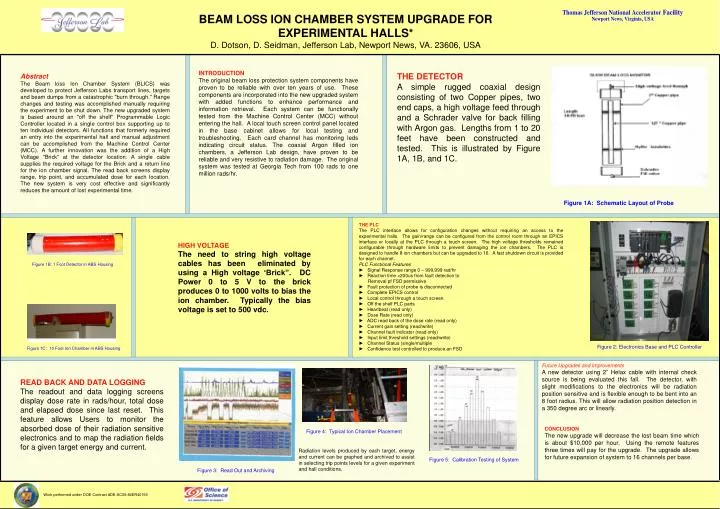
BEAM LOSS ION CHAMBER SYSTEM UPGRADE FOR EXPERIMENTAL HALLS* D. Dotson, D. Seidman, Jefferson Lab, Newport News, VA. 23606, USA INTRODUCTION The original beam loss protection system components have proven to be reliable with over ten years of use. These components are incorporated into the new upgraded system with added functions to enhance performance and information retrieval. Each system can be functionally tested from the Machine Control Center (MCC) without entering the hall. A local touch screen control panel located in the base cabinet allows for local testing and troubleshooting. Each card channel has monitoring leds indicating circuit status. The coaxial Argon filled ion chambers, a Jefferson Lab design, have proven to be reliable and very resistive to radiation damage. The original system was tested at Georgia Tech from 100 rads to one million rads/hr. THE DETECTOR A simple rugged coaxial design consisting of two Copper pipes, two end caps, a high voltage feed through and a Schrader valve for back filling with Argon gas. Lengths from 1 to 20 feet have been constructed and tested. This is illustrated by Figure 1A, 1B, and 1C. Abstract The Beam loss Ion Chamber System (BLICS) was developed to protect Jefferson Labs transport lines, targets and beam dumps from a catastrophic "burn through." Range changes and testing was accomplished manually requiring the experiment to be shut down. The new upgraded system is based around an "off the shelf" Programmable Logic Controller located in a single control box supporting up to ten individual detectors. All functions that formerly required an entry into the experimental hall and manual adjustment can be accomplished from the Machine Control Center (MCC). A further innovation was the addition of a High Voltage "Brick" at the detector location. A single cable supplies the required voltage for the Brick and a return line for the ion chamber signal. The read back screens display range, trip point, and accumulated dose for each location. The new system is very cost effective and significantly reduces the amount of lost experimental time. Figure 1A: Schematic Layout of Probe THE PLC The PLC interface allows for configuration changes without requiring an access to the experimental halls. The gain/range can be configured from the control room through an EPICS interface or locally at the PLC through a touch screen. The high voltage thresholds remained configurable through hardware limits to prevent damaging the ion chambers. The PLC is designed to handle 8 ion chambers but can be upgraded to 16. A fast shutdown circuit is provided for each channel. PLC Functional Features ► Signal Response range 0 – 999,999 rad/hr ► Reaction time <200us from fault detection to Removal pf FSD permissive ► Fault protection of probe is disconnected ► Complete EPICS control ► Local control through a touch screen ► Off the shelf PLC parts ► Heartbeat (read only) ► Dose Rate (read only) ► ADC read back of the dose rate (read only) ► Current gain setting (read/write) ► Channel fault indicator (read only) ► Input limit threshold settings (read/write) ► Channel Status (single/multiple ► Confidence test controlled to produce an FSD HIGH VOLTAGE The need to string high voltage cables has been eliminated by using a High voltage ‘Brick”. DC Power 0 to 5 V to the brick produces 0 to 1000 volts to bias the ion chamber. Typically the bias voltage is set to 500 vdc. Figure 1B: 1 Foot Detector in ABS Housing Figure 2: Electronics Base and PLC Controller Figure 1C: 10 Foot Ion Chamber in ABS Housing Future Upgrades and Improvements A new detector using 2” Helax cable with internal check source is being evaluated this fall. The detector, with slight modifications to the electronics will be radiation position sensitive and is flexible enough to be bent into an 8 foot radius. This will allow radiation position detection in a 350 degree arc or linearly. READ BACK AND DATA LOGGING The readout and data logging screens display dose rate in rads/hour, total dose and elapsed dose since last reset. This feature allows Users to monitor the absorbed dose of their radiation sensitive electronics and to map the radiation fields for a given target energy and current. CONCLUSION The new upgrade will decrease the lost beam time which is about $10,000 per hour. Using the remote features three times will pay for the upgrade. The upgrade allows for future expansion of system to 16 channels per base. Figure 4: Typical Ion Chamber Placement Radiation levels produced by each target, energy and current can be graphed and archived to assist in selecting trip points levels for a given experiment and hall conditions. Figure 5: Calibration Testing of System Figure 3: Read Out and Archiving Work performed under DOE Contract #DE-AC05-84ER40150


