Download
1 / 50
500 likes | 673 Views
Feasibility of Energy Recovery in Conjunction With The Application of A Redesigned Central Cooling And Heating Plant. Outline. Introduction/Background Existing Conditions Problem Statement Energy Recovery System (ERS) Design Central Plant Redesign Electrical Analysis Structural Analysis

E N D
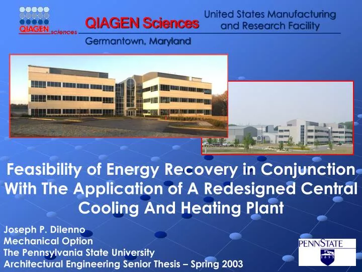
Feasibility of Energy Recovery in Conjunction With The Application of A Redesigned Central Cooling And Heating Plant
Outline • Introduction/Background • Existing Conditions • Problem Statement • Energy Recovery System (ERS) Design • Central Plant Redesign • Electrical Analysis • Structural Analysis • Life-Cycle Cost Analysis • Conclusions and Recommendations
Project Team • Owner: QIAGENSciences, Inc. • Architect: Capital Design Assocs., Inc. • CM: Whiting-Turner • GC: CDI Engineering Group • Mech. Contractor: Pierce Associates • MEP Engineer: Herzog-Hart Corp. • Structural: Cagley and Associates
Outline • Introduction/Background • Existing Conditions • Problem Statement • Energy Recovery System (ERS) Design • Central Plant Redesign • Electrical Analysis • Structural Analysis • Life-Cycle Cost Analysis • Conclusions and Recommendations
Existing Overall Conditions • Location: 118 Germantown Road, Germantown, Maryland • Size: 213,000 Ft2 • Cost: $52.5 Million • Use : R & D; storage; administrative
Building 1 Building 2
Existing Mechanical Conditions • Air Side • 16 Air-handling Units (4,770 to 46,105 CFM) • 5 – 100% Outdoor air units (4,770 to 18,105 CFM) • Heating Plant • 2 – 400 BHP Fire-tube steam boilers • 2 – 400 GPM shell and tube HX • Cooling Plant • 2 – 900 ton electric driven centrifugal chillers • Primary-secondary distribution
Outline • Introduction/Background • Existing Conditions • Problem Statement • Energy Recovery System (ERS) Design • Central Plant Redesign • Electrical Analysis • Structural Analysis • Life-Cycle Cost Analysis • Conclusions and Recommendations
Problem Statement • Substantial energy usage • No energy recovery Existing 100% Outdoor Air Air-Handling Unit
Problem Statement • Peak electric costs coincide with peak cooling loads • No approach for demand reduction Existing Chiller Plant
Outline • Introduction/Background • Existing Conditions • Problem Statement • Energy Recovery System (ERS) Design • Central Plant Redesign • Electrical Analysis • Structural Analysis • Life-Cycle Cost Analysis • Conclusions and Recommendations
Energy Recovery System (ERS) • 4 existing 100% outdoor air units modified with total energy recovery wheels • SEMCO TE3 EXCLU-SIEVE® Total Energy Wheels selected • Cross-contamination issues
ERS Energy Analysis • Carrier’s Hourly Analysis Program (HAP) V4.10 • Peak cooling load reduced from 1,045 tons to 885 tons, a reduction of 160 tons • Peak preheating load reduced from 7,015 MBH to 4,650 MBH, a 2,365 MBH reduction
ERS First Cost • Cost information was obtained from Spencer Goland at Rotor Source, Inc.
Outline • Introduction/Background • Existing Conditions • Problem Statement • Energy Recovery System (ERS) Design • Central Plant Redesign • Electrical Analysis • Structural Analysis • Life-Cycle Cost Analysis • Conclusions and Recommendations
Central Plant Redesign Modeling • DOE 2 electric chiller modeling • Correction factors based on chilled water and condenser water temperatures • Regression coefficients • Capacity correction • Efficiency correction
Central Plant Redesign Modeling Marley Cooling Tower Curves • Cooling Tower Modeling • Curve fitting using manufacturer plots • Linear regressions for each constant range on plot • Condenser water temperature is a function of range and wet bulb temperature • Curves for full and half speed
Central Plant Redesign Modeling Bell & Gossett Pump Curve • Pump Modeling • Curve fit existing plot • Head and efficiency as a function of flow • Affinity laws for variable speed pumping • Head is function of flow rate and motor speed
Central Plant Redesign Modeling • Gas-fired absorption chiller-heater modeling • Unique aspect of central plant modeling • Chiller-heaters can provide simultaneous heating and cooling • York YPC double-effect absorption chiller-heater model • Curve fit part load performance charts provided by York for individual and simultaneous operation Individual Performance (York) Individual Performance (EES) Simultaneous Performance (York) Simultaneous Performance (EES)
Central Plant Redesign Energy Analysis • EES produces hourly energy consumption for central plant components • Microsoft Excel is used to calculate energy costs • Utility rates are taken from service providers
Central Plant Redesign Energy Analysis • Peak demand kW reductions • Central plant gas usage • kW Demand charge reductions • Total Annual Energy Costs
Central Plant Redesign First Cost Analysis • First cost information for chillers from Jim Thompson at York International • R.S. Means
Outline • Introduction/Background • Existing Conditions • Problem Statement • Energy Recovery System (ERS) Design • Central Plant Redesign • Electrical Analysis • Structural Analysis • Life-Cycle Cost Analysis • Conclusions and Recommendations
Electrical Analysis • Why look at the electrical system? • 2 direct points of connection on main switchgear #2 for existing electric driven chillers • Existing electrical loads on switchgear #2 • Power Panel PP4 • Chillers #1 and #2 • Emergency Distribution Panel EDP #3 • Serves 4 Emergency Motor Control Centers (EMCC) • Spare connection • kVA demand calculated for load on switchgear • Feeder sizing done for each case • Calculations done as per NEC standards
Electrical Analysis • Case A shows no reduction in electrical service • Case C reduces load by 558 kVA • 2500 kVA transformer downsized to 2000 kVA • $6,015 savings • Wire size reduced • $8,960 savings
Outline • Introduction/Background • Existing Conditions • Problem Statement • Energy Recovery System (ERS) Design • Central Plant Redesign • Electrical Analysis • Structural Analysis • Life-Cycle Cost Analysis • Conclusions and Recommendations
Structural Analysis • Why look at the structural systems? • Cooling tower framing • Equipment foundations • Centrifugal chiller foundation design • 4 times the equipment weight in concrete for vibration • Reinforcing for temperature and shrinkage • Absorption chiller-heater foundation design • Few moving parts, vibration not critical • Foundation needs to support equipment operating weight
Structural Analysis • Design Parameters • ACI 318-02 • Shrinkage and Temperature Reinforcing • Wide Beam Shear • Flexure • Punching Shear • Existing centrifugal chiller foundation • 36” depth • 2 chillers weighing 27,000 lbs each • Case A centrifugal chiller foundation • Use 36” depth as in existing building • 2 chillers weighing 23,400 lbs each • Case C absorption chiller-heater foundation • Use 12” depth • 1 chiller-heater weighing 65,500 lbs • Chiller-heater foundation depth reduced 24” from centrifugal chiller foundation despite weight increase of over 42,000 lbs • Reduced depth saves $1,840 compared to base building and Case A foundations • Concrete costs • Reinforcing steel costs
Outline • Introduction/Background • Existing Conditions • Problem Statement • Energy Recovery System (ERS) Design • Central Plant Redesign • Electrical Analysis • Structural Analysis • Life-Cycle Cost Analysis • Conclusions and Recommendations
Life-Cycle Cost Analysis • Used to determine most attractive redesign option • First cost information combined with annual energy costs calculated in central plant redesigns • First costs for ERS design, central plant equipment, structural and electrical redesigns • Analysis Method • 20 year life cycle • ERS replacement at 10 years • NIST Energy Price Indices • Constant dollar approach using 3.9% real discount rate
Life-Cycle Cost Analysis • Case C hybrid plant has lowest LCC • Result of reduced annual energy costs • $864,475 savings over base building • $230,756 savings over Case A redesign • Case A redesign has instant payback • Case C payback; 9 months • Case C net savings over Case A; $133,132 • Difference in LCC savings and first cost savings of 2 cases
Outline • Introduction/Background • Existing Conditions • Problem Statement • Energy Recovery System (ERS) Design • Central Plant Redesign • Electrical Analysis • Structural Analysis • Life-Cycle Cost Analysis • Conclusions and Recommendations
Conclusions and Recommendations • Energy Recovery System Design • Effective response to high energy consumption of 100% outdoor air units • Decreases size of central cooling and heating plant • Central Plant Redesign • Case B central plant first cost and required area too high; not a feasible option • Cases A and C both provide significant life-cycle cost savings • Case C hybrid plant shows best annual energy costs
Conclusions and Recommendations • Final Recommendation • Implement Case C gas-electric hybrid central plant redesign • Short payback period attractive to owner • Highest net savings of all options evaluated • Flexibility of using either gas-fired chiller-heater or electric driven centrifugal as primary chiller • Future electric utility rates may be more or less favorable
Acknowledgements AE Faculty William P. Bahnfleth, Ph.D., P.E. Stanley A. Mumma, Ph.D., P.E. James D. Freihaut, Ph.D. Walt Schneider, P.E. Industry Professionals Dave Johnson, P.E. – QIAGEN Sciences, Inc. John Saber, P.E, – Encon Group, Inc. Jim Thompson – York International Corporation Spencer Goland – Rotor Source, Inc. Cindy Cogil – Smith Group 5th Year AE Students Andy Tech – Mechanical Jim Meacham – Mechanical/CM 242 South Atherton St. – Multi-disciplinary Family, Friends, and People I Forgot
ERS Wheel Selection • SEMCO provided performance charts used to select proper wheel size • Selection based on supply and return air quantities • Return air from general room exhaust, not fume hoods • Optimum face velocity of 800 FPM across wheel
ERS Performance • Controlling cross-contamination is critical for laboratory spaces • 3Å Molecular Sieve Desiccant • Adjustable Purge Air Section • Independent Testing Results Microscopic view of 3Å molecular sieve Purge Air Schematic Testing Results
Electrical Analysis • kVA demand calculations • Incorporate demand factor and voltage
Electrical Analysis • kVA demand is calculated for load on switchgear • NEC Table 430-150 used to determine the full load current for the motors connected to EMCC’s • Feeder sizing done for each case • NEC Table 310-16 used for wire ampacity • Branch Conductor • NEC 430-22 D at 125% of the full load current • Overload Protection • NEC 430-31 and NEC Table 430-152 ; time delay fuses @ 175% FLC • Disconnect • NEC 430-110 at 115% of full load current • Air-conditioning and refrigeration equipment analyzed per NEC 440 • Grounding sized according to NEC Table 250-94 • Conduit sized according to NEC Chapter 9
Structural Analysis • Reinforcing design • Chapter 7 specifies minimum area of steel for shrinkage and temperature
Structural Analysis • Wide beam shear check • Chapter 11.3 – Shear strength for non-prestressed members • Chapter 11.12 – Special provisions for slabs and footings • Chapter 15.4 – Shear in footings
Structural Analysis • Flexure check • Chapter 15.4 – Moments in footings • Chapter 12 – Development and splices of reinforcement
Structural Analysis • Punching shear check • Assumes 8”x8” vibration isolation pads at 4 corners • Chapter 15.5 – Shear in footings • Chapter 11.12 – Special provisions for slabs and footings
Life-Cycle Cost Analysis • First cost information • Manufacturer cost data • R.S. Means cost data Base building first cost Case A first cost Case C first cost