Download
1 / 24
240 likes | 437 Views
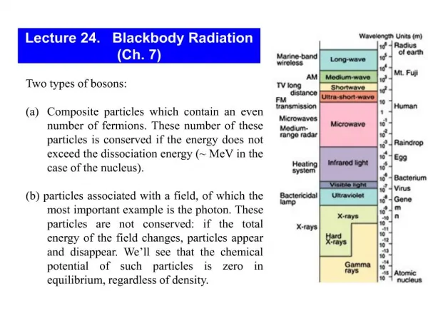
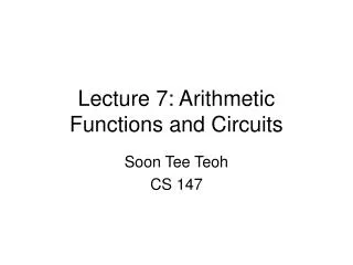
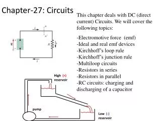
Lecture 7 Circuits Ch. 27. Cartoon -Kirchhoff's Laws Warm-up problems Topics Direct Current Circuits Kirchhoff's Two Rules Analysis of Circuits Examples Ammeter and voltmeter RC circuits Demos Three bulbs in a circuit Power loss in transmission lines Resistivity of a pencil

E N D
Lecture 7 Circuits Ch. 27 • Cartoon -Kirchhoff's Laws • Warm-up problems • Topics • Direct Current Circuits • Kirchhoff's Two Rules • Analysis of Circuits Examples • Ammeter and voltmeter • RC circuits • Demos • Three bulbs in a circuit • Power loss in transmission lines • Resistivity of a pencil • Blowing a fuse
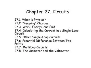
Direct Current Circuits • The sum of the potential drops around a closed loop is zero. This follows from energy conservation and the fact that the electric field is a conservative force. 2. The sum of currents into any junction of a closed circuit must equal the sum of currents out of the junction. This follows from charge conservation.
Example (Single Loop Circuit) No junction so we don’t need that rule. How do we apply Kirchoff’s rule? Must assume the direction of the current – assume clockwise. Choose a starting point and apply Ohm’s Law as you go around the circuit. • Potential across resistors is negative • Sign of E for a battery depends on assumed current flow • If you guessed wrong on the sign, your answer will be negative Start in the upper left hand corner.
Note that we could have simply added all resistors and get the Req. and added the EMFs to get the Eeq. And simply divided. Now let us put in numbers. Suppose: amp Sign of EMF Battery 1 current flows from - to + in battery +E1 Battery 2 current flows from + to - in battery -E2 In 1 the electrical potential energy increases In 2 the electrical potential energy decreases amp Suppose: amp We get a minus sign. It means our assumed direction of current must be reversed.
Example with numbers Quick solution: Question: What is the current in the circuit? Write down Kirchoff’s loop equation. Loop equation Assume current flow is clockwise. Do the batteries first – Then the current.
Example with numbers (continued) Question: What are the terminal voltages of each battery? 12V: 2V: 4V:
Multiloop Circuits Find i, i1, and i2 We now have 3 equations with 3 unknowns. Kirchoff’s Rules • in any loop • at any junction multiply by 2 multiply by 3 subtract them Rule 1 – Apply to 2 loops (2 inner loops) a. b. Rule 2 a. Find the Joule heating in each resistor P=i2R. Is the 5V battery being charged?
Method of determinants for solving simultaneous equations Cramer’s Rule says if : Then,
Method of determinants using Cramers Rule and cofactors Also use this to remember how to evaluate cross products of two vectors. For example solve for i You try it for i1 and i2. See inside of front cover in your book on how to use Cramer’s Rule.
Another example Loop 2 Find all the currents including directions. i i i2 i1 Loop 1 i i i2 Loop 1 Multiply eqn of loop 1 by 2 and subtract from the eqn of loop 2 Loop 2
Rules for solving multiloop circuits • Replace series resistors or batteries with their equivalent values. • Choose a direction for i in each loop and label diagram. • Write the junction rule equation for each junction. • Apply the loop rule n times for n interior loops. • Solve the equations for the unknowns. Use Cramer’s Rule if necessary. • Check your results by evaluating potential differences.
3 bulb question The circuit above shows three identical light bulbs attached to an ideal battery. If the bulb#2 burns out, which of the following will occur? Bulbs 1 and 3 are unaffected. The total light emitted by the circuit decreases. Bulbs 1 and 3 get brighter. The total light emitted by the circuit is unchanged. Bulbs 1 and 3 get dimmer. The total light emitted by the circuit decreases. Bulb 1 gets dimmer, but bulb 3 gets brighter. The total light emitted by the circuit is unchanged. Bulb 1 gets brighter, but bulb 3 gets dimmer. The total light emitted by the circuit is unchanged. Bulb 1 gets dimmer, but bulb 3 gets brighter. The total light emitted by the circuit decreases. Bulb 1 gets brighter, but bulb 3 gets dimmer. The total light emitted by the circuit decreases. Bulb 1 is unaffected, but bulb 3 gets brighter. The total light emitted by the circuit increases. None of the above.
When the bulb #2 is not burnt out: For Bulb #1 For Bulb #2 For Bulb #3
When the bulb #2 is burnt out: For Bulb #1 Before total power was For Bulb #2 After total power is So, Bulb #1 gets dimmer and bulb #3 gets brighter. And the total power decreases. f) is the answer. For Bulb #3
How does a capacitor behave in a circuit with a resistor? Charge capacitor with 9V battery with switch open, then remove battery. Now close the switch. What happens?
V(t) Discharging a capacitor through a resistor Potential across capacitor = V = just before you throw switch at time t = 0. Potential across Resistor = iR at t > 0. What is the current I at time t? or
What is the current I at time t? Time constant =RC Integrating both the sides At t=0, Q=Q0
i t RC What is the current? Ignore - sign
How the charge on a capacitor varies with time as it is being charged What about charging the capacitor? Same as before Note that the current is zero when either the capacitor is fully charged or uncharged. But the second you start to charge it or discharge it, the current is maximum.
Instruments Galvanometers: a coil in a magnetic field that senses current. Ammeters: measures current. Voltmeter: measures voltage. Ohmmeters: measures resistance. Multimeters: one device that does all the above. Galvanometer is a needle mounted to a coil that rotates in a magnetic field. The amount of rotation is proportional to the current that flows through the coil. Symbolically we write Usually when
Ohmmeter Adjust Rs so when R=0 the galvanometer read full scale.
Ammeter The idea is to find the value of RS that will give a full scale reading in the galvanometer for 5A Very small Ammeters have very low resistance when put in series in a circuit. You need a very stable shunt resistor.
Voltmeter Use the same galvanometer to construct a voltmeter for which full scale reading in 10 Volts. What is the value of RS now? So, the shunt resistor needs to be about 20KW. We need Note: the voltmeter is in parallel with the battery.