Download
1 / 36
360 likes | 520 Views
Large-scale Cryogenic Gravitational-wave Telescope, LCGT. Keiko Kokeyama University of Birmingham. 23 rd July 2010 Friday Science. General introduction of LCGT project Introduction of gravitational waves (GWs) Introduction of LCGT Science goal and impact Technical features

E N D
Large-scale Cryogenic Gravitational-wave Telescope, LCGT Keiko Kokeyama University of Birmingham 23rd July 2010 Friday Science
General introduction of LCGTproject Introduction of gravitational waves (GWs) Introduction of LCGT Science goal and impact Technical features Underground, Seismic isolation system, Cryogenic, Optical configuration, Operation modes Technical background CLIO project as a LCGT prototype Contents Photos and plots are from “LCGT design document, “ CLIO/LCGT talks by Miyoki-san and Yamamoto-san, and “Study report on LCGT interferometer observation band” 0/28
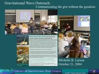
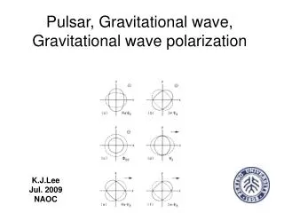
y x Gravitational Waves • Ripples of spacetime propagating at the speed of light. • Changing the distances between free particles. Coalescences of neutron star binaries, Supernova, BH coalescences, etc. • Einstein predicted its existence as a consequence of the general relativity in 1916. • Its existence is verified indirectly by the binary-neutron star observation, however, the direct detection has not been successful yet. Significances of the direct detection • Experimental verification of the general relativity • The GW astronomy 1/28
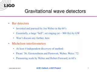
Gravitational Wave Detectors • Laser interferometer (ifo) type • GW changes the mirror positions • The path length difference is detected as the phase difference between the two paths • GW has a very weak interaction to matters - very small path length change Mirror Mirror Beam- splitter Bright Laser Dark Photo detector Super accurate measurement to detect 10-20m change per 1 m 2/28
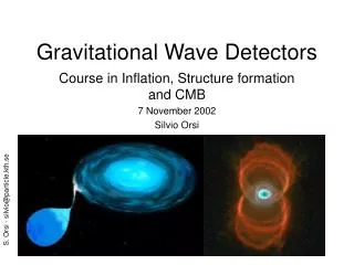
Large Scale ground-based GW detectors The 1st Generation Detectors LIGO GEO600 TAMA300 VIRGO Upgrading to the 2nd Generation Detectors Advanced LIGO, Advanced VIRGO, GEO HF, LCGT 3/28
LCGT project • On 22nd June, the Japanese Next Generation Detector, LCGT was funded • 9.8 billion yen (£75M) for three years including 2010. • selected one of the projects for the forefront-research-development-strategic subsidy (40 billion yen in total) of Ministry of education, culture, sports, science and technology, Japan • The purpose of this subsidy is to develop the environment for the young or female scientists, and internationally high level researches • Further budget is being requested to run the project after the 3rd year. The result will be appear in August. 4/28
Establish the GW astronomy Main goal: to detect gravitational waves from neutron star binaries (1.4 solar mass) at about 200 Mpc with > S/N 8 Expecting a few events in a year from: Coalescences of neutron star binaries Goal sensitivity: h=3 ×10-24 [m/rtHz] at 100Hz Scientific Goals 5/28
GW detector network • LCGT plays a role of Asia-Oceania center among other detectors Best sensitivity direction for LCGT LIGO Hanford LIGO Livingston VIRGO The good-sensitivity directions are complementary for other detectors 6/28
Technical Features of LCGT • Underground Site • (2) Seismic isolation system • (3) Cryogenic Technique • Thermal noise design, Substrate of test mass • (4) Optical configuration • Four configurations and the observation plan 7/28
(1) Underground Site 8/28
(1) Underground Site 9/28
(1) Underground Site 10/28
(1) Underground Site More than 2 orders of magnitude better than TAMA site The variance of 46 hours is about 0.1~0.2 degrees without temperature-controlling 11/28
(2) Seismic isolation system • Requirement: -190 dB at 3 Hzincluding the suspension part (*) and seismic isolation system • Seismic level in Kamioka is 10-9 m/rtHz at 3Hz • Sensitivity requirement is 3x10-18 m/rtHz at 3 Hz • The seismic isolation system (room temperature) is required • -130 dB isolation (*) Test masses are suspended so that they act as free masses. Suspensions play a role of isolating the seismic motion, too. 12/28
(2) Seismic isolation system • Inverted pendulum • Three GAS (Geometric anti-spring) filters • This system achieves isolation ratios of: • -160dB for horizontal (w/ 4stages) at 3 Hz • -140 dB for vertical (w/ 3 stages) at 3 Hz • These satisfy the requirement ↓ 2-stage suspension (Low temperature) 13/28
(3) Cryogenic • We want to reduce the thermal noise • Thermal noise is… • To reduce the thermal noise, the main mirrors and suspension are cooled down to 20 K by refrigerators • sapphire f 250 ×150mm, 30kg 14/28
(3) Cryogenic • Heat links are used to release the heat occurred by the laser beam on the test-masses SAS, 300 K Heat link 1W, 7 ×f1mm, Al Heat link 1W, 5 ×f3mm Al Bolfur wire 40cm, f1.8mm Recoil Masses will be suspended by Sapphire or Al wires 10K Sapphire wire, 860 mW 40cm, f1.8mm 20K 8K, 100K • Similar type to CLIO refrigerator (Sumitomo Heavy Industries Ltd, Pulse-tube refrigerator) 15/28
(4) Optical configuration Main IFO 16/28
(4) Optical configuration Main IFO • Resonant-Sideband-Extraction (RSE) • In addition to the Fabry-Perot (FP) arm cavities, Power recycling and signal extraction cavities (PRC and SEC, respectively) are added to the interferometer • Advantages in capability of high laser power in arm cavities and flexibility in observation band FP cavity FP cavity PRC SEC 17/28
Operation modes (4) Optical configuration • BRSE: Broad band operation The carrier laser light is anti-resonant in SEC. Detector observation band is tuned to have a maximum sensitivity for neutron-star inspiral events. • DRSE: Detuned RSE. Detuning is a technique to increase detector sensitivity only in a slightly narrow frequency band. It is realized by controlling the SEC length between resonance and anti-resonance condition for the carrier laser beam. • V-BRSE: Broad band operation + slightly off resonance in the arm cavity • V-DRSE: Detuned operation+ slightly off resonance in the arm cavity FP PRC FP SEC 18/28
(4) Optical configuration Operation modes BRSE configuration has wider band. It can provides longer observation duration for an inspiral event. It is good for extracting information from observed waveforms, in accuracy of estimated binary parameters, the arrival time, and so on. • DRSE configuration has the best floor-level sensitivity at around 100 Hz, and the good observable distance for neutron-star inspiral events. Therefore the detuned configurations have advantages in the first detection and expected number of events. V-BRSEand V-DRSEhave both advantages. 19/28
(4) Optical configuration Operation Strategy Operate in the V-DRSEmode first for earlier detection of gravitational-wave signals After the first few detections, they will switch to the V-BRSE mode. 20/28
Technical Background Suspended 4m RSE 21/28
CLIO • In Kamioka mine • Prototype ifo for LCGT • To demonstrate the thermal noise reduction using cryogenic technique • 100m base-line unrecombined Fabry-Perot Michelson interferometer Beam-splitter Fabry-Perot cavity Fabry-Perot cavity 22/28
Cryogenic in CLIO • 2008: 300K design sensitivity achieved. • 300K mirror thermal noise dominates the sensitivity around 150Hz. • 2009: Both near mirrors were cooled at about 20K. • 2010: Sensitivity around 150Hz were improved. • Total mirror thermal noise were reduced. The suspended sapphire mirror (f100×60, 2kg) 6-stage vibration isolation (3 stages in 300K, 3 stages in cryogenic) Low vibration refrigerator 24/28
Displacement in November 2008 • Almost the thermal noise limited at 300K (4/2008 to 12/2008) • Clio displacement touched the predicted thermal noise level Sapphire mirror themal noise Suspension thermal noise (20-80 Hz) 25/28
Reduction of Mirror Thermo-Elastic Noise • It took 250 hours for cooling the mirror. • The near mirrors were cooled at 16.4k and inner shield was cooled at 11.5k. • The outer shield of the mirror tank and center of the cryogenic vacuum pipe were cooled at 69k and 49k, respectively. • Two near mirrors are cooled down to 20 K 26/28
Reduction of Mirror Thermo-Elastic Noise • CLIO has finally demonstrated the reduction of the thermal noise onsapphire mirrors around 200 Hz 27/28
Summary • LCGT • Just funded! The overview of LCGT project such as underground site, Seismic isolation system, cryogenic, optical configuration were reviewed. • CLIO • As the prototype for LCGT, CLIO successfully demonstrated the thermal noise reduction. Cryogenic, underground techniques are established for LCGT • Note: • Some parameters and materials are still under discussion toward the final design 28/28
Suppliment slide (3) Reduction of Suspension Thermal Noise
Vacuum tanks • Vacuum level • 2 x 10⁻⁷ Pa • Vacuum duct • 3km length • 1m diameter • steinless steel