Download
1 / 42
430 likes | 631 Views
InfiniteReality: A Real-Time Graphics System. John S. Montrym, Daniel R. Baum, David L. Dignam, and Christopher J. Migdal Silicon Graphics Computer Systems Presented by Jamison Daniel. Introduction. InfiniteReality Design Goals. Able to handle extremely large texture databases

E N D
InfiniteReality: A Real-Time Graphics System John S. Montrym, Daniel R. Baum, David L. Dignam, and Christopher J. Migdal Silicon Graphics Computer Systems Presented by Jamison Daniel
InfiniteReality Design Goals • Able to handle extremely large texture databases • Maintain control over frame rendering time • Deliver 60Hz steady frame rate high-quality rendering of complex scenes.
InfiniteReality Rendering Performance • 7,000,000 lighted, textured, antialiased triangles per second • 710,000,000 textured antialiased pixels filled per second.
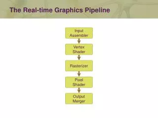
Native Support for OpenGL • InfiniteReality system is a sort-middle architecture. • A sort-last architecture is not well suited to supporting OpenGL. Why?
Three Distinct Board Types • Geometry Board • Raster Memory Board • Display Generator Board
The Geometry Board • Host Computer Interface • Command Interpretation and Geometry Distribution Logic • Four Geometry Engine processors in a MIMD arrangement.
Host Interface • Compiled display list objects are stored in host memory in such a way that leaf display objects can be “pulled” into the graphics subsystem using DMA transfers set up by the Host Interface Processor.
Geometry Distributor • The Geometry Distributor passes incoming data and commands from the Host Interface Processor to individual Geometry Engines for further processing. • Least-busy distribution scheme.
Geometry Engines • The Geometry Engine is a single instruction multiple datapath (SIMD) arrangement of three floating point cores, each of which comprises an ALU and a multiplier plus a 32 word register. • A 2560 word on-chip memory holds elements of OpenGL state.
Geometry Engine • Each of the three cores can perform two reads and one write per instruction to working memory. • The working memory allows data to be shared easily among cores.
Pipeline Considerations • InfiniteReality implements four pipeline stages in the floating point arithmetic blocks. • When increased to more than four stages, the clock speeds improved but the total performance did not. Why?
Benchmarking Considerations • Often machine performance is expressed in terms of vertex rates for triangles in long strips. • Application performance is much more likely to be determined by how well a system handles very short strips, with frequent mode changes.
Solution: Distinct Code Modules • To accelerate mode change processing, InfiniteReality divides the work associated with individual OpenGL modes into distinct code modules. • A table consisting of pointers to the currently active modules is maintained in the Geometry Engine working memory.
Geometry-Raster FIFO • A FIFO large enough to hold 65536 vertexes is implemented in SDRAM. • The merged geometry engine output is written, through the SDRAM FIFO, to the Vertex Bus.
Raster Memory Board • Each Raster Memory Board comprises a single fragment generator with a single copy of texture memory to allocate 512 bits per pixel to a 1280x1224 framebuffer.
Vertex Bus • The InfiniteReality system employs a Vertex Bus to transfer only screen space vertex information. • Supports the OpenGL triangle strip and triangle fan constructs, so the Vertex Bus load corresponds closely to the load on the host-to-graphics bus.
Increased Transform-Limited Triangle Rates • The Geometry Engine triangle strip workload is reduced by around 60% by not calculating triangle setup information. • COST: Hardware to assemble screen space primitives and compute parameter slopes must be incorporated into the Fragment Generators.
Fragment Generators • Connected vertex streams are received and assembled into triangle primitives.
A Fragment Generator • The Scan Converter (SC) and Texel Address Calculator (TA) perform scan conversion, color and depth interpolation, perspective correct texture coordinate interpolation and LOD computation.
A Fragment Generator • Each texture memory controller (TM) performs the texel lookup in its four attached SDRAMS, given texel addresses from the TA • The TMs combine redundant texel requests from neighboring fragments to reduce SDRAM access.
A Fragment Generator • The TMs forward the resulting texel values to the appropriate TF for texture filtering, texture environment combination with interpolated color, and fog application. • Since there is only one copy of the texture memory distributed across all the texture SDRAMs, there must exist a path from all 32 texture SDRAMs to all Image Engines.
Image Engines • Fragments output by a single Fragment Generator are distributed equally among the 80 Image Engines owned by that generator. • Each Image Engine controls a single 256K x 32 SDRAM that comprises its portion of the framebuffer.
Framebuffer Tiling • The Fragment Generator scan-conversion completes all pixels in a two pixel wide vertical strip before proceeding to the next strip for every primitive. • To keep the Image Engines from limiting fill rate on large primitives, all Image Engines must be responsible for part of every vertical strip owned by their Fragment Generator.
Display Hardware • Each of the 80 Image Engines on the Raster Memory boards drives one or two bit serial signals to the Display Generator board. • The base display system consists of two channels, expendable to eight.
Virtual Textures • Texture data that cover the entire world at one meter corresponds to a texture size of 40,000,000 x 20,000,000 texels. • The InfiniteReality system provides hardware and software support for very large virtual textures that approach this size.
Solution: Mip-Map ? • The amount of texture data that can be viewed at one time is limited by the resolution of the display monitor. • WORST CASE: Occurs when the texture is viewed from directly above. However, in most applications the database is viewed obliquely and in perspective.
Better Solution: Clip-Map • A clip-map pyramid which is exactly the same as the coarser levels of the original mip-map. • A clip-map stack which holds a subset of the data in the original mip-map for the finest levels of detail.
Clip-Map • The clip-map stack levels all have the same size in texture memory, but each successively coarser level covers four times the source image area of the immediately finer level. • The clip-map stack levels are centered on a common point.
Clip-Map Stack Management • Because the clip-map stack does not contain the entire texture the position of the clip-map stack needs to be updated to track the center of the viewer’s gaze. • As the viewer’s gaze moves, new texture data is loaded into the texture memory to replace the texture data that is no longer required.
Guaranteed LOD ? • The InfiniteReality texture subsystem detects when texture is requested at a higher resolution than is available in texture memory. • It substitutes the best available data which is data at the correct spatial position, but at a coarser LOD than requested.
32K x 32K texture represented as a 2K x 2K clip-map. • The clip-map representation requires about 1/64 the storage of the equivalent 32K x 32K mip-map!
Scene Load Management • Regardless of the performance levels of a graphics system, there may be times when there are insufficient hardware resources to maintain a real-time frame update rate. • These cases occur when the pipeline becomes either geometry or fill rate limited.
Pipeline Performance Statistics • Counters are maintained in the Geometry-Raster FIFO that monitor stall conditions on the Vertex Bus as well as wait conditions upstream in the geometry path.
Solution: Geometry Limited • The application temporarily reduces the complexity of objects being drawn starting with those objects that are most distant from the viewer. • This allows the application to reduce the polygon count being sent to the pipeline without severely impacting the visual fidelity of the scene. • Would this help with a fill limited pipeline?
Solution: Fill Limited • Fill requirements are evaluated and a scene is rendered to the framebuffer at a reduced resolution such that drawing completes in less than one frame time. • Prior to display on the monitor, the image is scaled up to the nominal resolution of the display format.
Resolution Changes • Can be changed in X or Y or both. • Magnifying the image back to the nominal display resolution is done digitally, just prior to display.
Conclusion • The InfiniteReality system achieves real-time rendering through a combination of raw graphics performance and capabilities designed to enable applications to achieve guaranteed frame rates. • This underlying performance, together with new rendering functionality like virtual texturing, paves the way for entirely new classes of applications.


![Real-Time Volume Graphics [05] Transfer Functions](https://cdn2.slideserve.com/5136640/real-time-volume-graphics-05-transfer-functions-dt.jpg)

![Real-Time Volume Graphics [02] GPU Programming](https://cdn3.slideserve.com/6316608/real-time-volume-graphics-02-gpu-programming-dt.jpg)