Download
1 / 35
350 likes | 516 Views
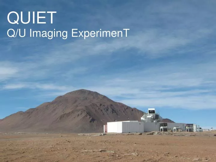
QUIET Q/U Imaging ExperimenT. QUIET Project Miami Physics Conference 2009 December 16 Raul Monsalve for the QUIET Collaboration University of Miami. What is QUIET ?. Radiotelescope that measures intensity and polarization of the CMB Located in Chile

E N D
QUIET Q/U Imaging ExperimenT
QUIET Project Miami Physics Conference 2009 December 16 Raul Monsalve for the QUIET Collaboration University of Miami
What is QUIET ? • Radiotelescope that measures intensity and polarization of the CMB • Located in Chile • Main science objective is to improve characterization of E-mode polarization and detect the difficult B-mode polarization • Two phases are planned. Phase-I is ongoing, started in August 2008. Phase II is planned to start in 2012, in a larger scale, improving the techniques learned during phase-I
QUIET Collaboration MANCHESTER U. CHICAGO OXFORD FERMILAB OSLO STANFORD COLUMBIA MPI-BONN JPL PRINCETON CALTECH U. MIAMI KEK SITE
Science Goals • We can measure the polarisation of the CMB the same way as for light • The Stokes parameters quantify the polarization properties of a light ray • I = no filter at all • Q = linear polarizer at 0 and 90° • U = linear polarizer at -45 and 45 ° • V = circular polarizer • I is just the temperature • Q and U combine to form E- and B-modes • No known physical process can generate V-polarized CMB radiation
Science Goals Status and Forecast on the EE and BB characterization
Site • Chajnantor Scientific Reserve in Chile at 5080 m above sea level • Among the best places for mm and submm astronomy • Access to CBI infrastructure • Accessible at all times • 1 hour drive from San Pedro de Atacama • Good sky coverage • For outside work bottled oxygen systems are used • Oxygen concentration in control room is increased ~27%
Mount • Inherited from CBI • Alt-Az axes • Rotation about optical axis (boresight axis) • Elevation range limited to 43 deg < el < 87 deg
Optics • Crossed Dragone design • 1.4 m primary and secondary mirrors • FWHM: 28 (Q) and 12 (W) arcmin
Horn Arrays • Conical corrugated feed horn arrays • Excellent beam symmetry • Low sidelobe response • Low cross-polarization • Broad frequency band • Typical FWHM of ~7 deg • Built by UM
OMTs • Splits incoming radiation into L and R • 20% bandwidth • Low loss • High isolation on the output ports to avoid temperature-to-polarization leakage
Detector Modules • Heart of the receiver • Polarimeter on a chip • Automated assembly and operation • Measuring of Q and U simultaneously in each pixel • Operate at ~20K
Module/OMTs Seven element demonstration array
Calibration Strategy Polarization Gain Stability MOON Once/7 days, Relative Gains, Angles NOISE SOURCE Once/1.5 hours, Relative Gains, Angles TAU A Once/2 days, Absolute Gains, Angles, Beams Temperature JUPITER Once/7 days, ∆T Gains, Beam SKY-DIP Once/1.5 hours, Relative Gains, Stability + supplemental measurements
Calibration Beam Shape using Jupiter
Calibration Tau A Gains Moon Polarization Fits
Observation Regions Patch Centers • Low foreground regions in coordination with ABS, Polarbear • (Multifrequency measurements for galactic foreground removal) • Distribution to allow continuous scanning 4x(15x15)=900 [deg²]
Telescope Operation during Q-Band Season Average 68.1% • Downtime mainly due to: • Mechanical Problems • Generator problems • Bad weather
Other Interesting Observations Galactic Center Polarization Maps with Q-Band Data (PRELIMINARY)
Other Interesting Observations Galactic Center Temperature Map with Q-Band Data (PRELIMINARY) QUIET WMAP
Phase-II Power-spectra Forecasts Current Performance Likely Improvement (noise, duty cycle, 1/f)
Appendix • Alternate technique to identify gravitational lensing effects (Zaldarriaga(1999), Hu(2002)) • Lens reconstruction: Lensing Deflection Field calculation from cross-correlation of E- and B-modes • Stronger constraints on cosmological parameters than using B-mode power spectrum • By measuring shape and amplitude of the Deflection power spectrum QUIET Phase-II can place constraints on parameters such as: • Neutrino mass (Maltoni, 2004) • Dark energy density (Stompor, 1999) • Spatial curvature (Stompor, 1999)
Summary • QUIET Science: • Experiment addressing fundamental questions in physics • Taking the CMB polarization knowledge to new levels • QUIET Status: • Largest HEMT-based focal plane array ever deployed, using state of the art MMIC packaging techniques • Phase-I observing and proposing Phase-II to start in 2012/2013
Systematic Errors • Overall signal size • Overall gain calibration • Beamsize calibration • Pointing error • Fake signal source • Instrumental I->Q/U : caused by OMT, 1% for Q-band. Negligible. • Gain fluctuations :up to 20% negligible for phase I. • E->B mixing source • Polarization angle : calibration better than 5% for phase I. • Optics cross polarization : only affects by order of ∆ө² • Q/U gain mismatch : relative gain between Q and U stable. • Patch geometry : finite patch, patch irregularity, pixelization
Systematic Errors E->B, Patch geometry