Download
1 / 13
130 likes | 265 Views
Lecture #17 EGR 277 – Digital Logic. Reading Assignment: Chapter 6 in Digital Design, 3 rd Edition by Mano. Timing Sequences So far we have designed circuits to: produce desired outputs for certain input combinations (combinational circuits)

E N D
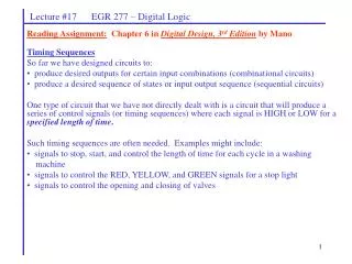
Lecture #17 EGR 277 – Digital Logic Reading Assignment: Chapter 6 in Digital Design, 3rd Edition by Mano • Timing Sequences • So far we have designed circuits to: • produce desired outputs for certain input combinations (combinational circuits) • produce a desired sequence of states or input output sequence (sequential circuits) • One type of circuit that we have not directly dealt with is a circuit that will produce a series of control signals (or timing sequences) where each signal is HIGH or LOW for a specified length of time. • Such timing sequences are often needed. Examples might include: • signals to stop, start, and control the length of time for each cycle in a washing • machine • signals to control the RED, YELLOW, and GREEN signals for a stop light • signals to control the opening and closing of valves
Lecture #17 EGR 277 – Digital Logic Decoders – Can be used to indicate when certain counts occur. Similarly, they can be used to start or stop events at certain times. Example: Design a decoder to detect when count 4 occurs. Example: Design a decoder to detect when counts 5, 7, or 15 occur. Also show how a 4x16 decoder could be used.
Lecture #17 EGR 277 – Digital Logic Example: Design a circuit that will output a signal that is HIGH for 3 seconds and LOW for 5 seconds.
Lecture #17 EGR 277 – Digital Logic Example: Design a circuit that will produce the following control signals.
Lecture #17 EGR 277 – Digital Logic Example: Design a traffic light controller with the following control signals. Notes: Whenever N/S Green or N/S Yellow are HIGH, E/W Red must also be HIGH. Whenever E/W Green or E/W Yellow are HIGH, N/S Red must also be HIGH. Handout: Traffic Light Controller schematic and PSPICE implementation Demo: Traffic Light Controller Circuit
Lecture #17 EGR 277 – Digital Logic • Shift Registers • Register - a group of binary storage cells (flip-flops) • Common Register Uses: • Temporary data storage and transfer • Parallel-to-serial and serial-to-parallel conversion • Data manipulation (complementation, rotation, etc) • Shift register - A register is often also referred to as a "shift register" since one of its • key functions involves the shifting of data through the register. Example: A register might be a group of 8 flip-flops used to store some binary data (byte or word). Sketch the circuit.
Lecture #17 EGR 277 – Digital Logic Example: A computer or microprocessor uses many types of registers, includingCPU, PC, SP, ALU (with registers A and B), C, D, E, F (general purpose), I/O registers at ports, etc. Sketch. Also show some common assembly language instructions involving registers.
Lecture #17 EGR 277 – Digital Logic Common register functions: (briefly illustrate each) 1) Serial shifting of data (SISO - right or SISO - left) (SISO = Serial-input, Serial-output) 2) Parallel input of data (PI) 3) Parallel output of data (PO) 4) Rotation of data (left or right)
Lecture #17 EGR 277 – Digital Logic Parallel load shift register using D flip-flops - illustrate
Lecture #17 EGR 277 – Digital Logic Parallel load shift register with an enable Discuss the limitations of the prior shift register. Show how to implement the register above using SR or JK flip-flops and then add an enable (ANDed with each input).
Lecture #17 EGR 277 – Digital Logic Serial-In Serial-Out (SISO) register Illustrate using D flip-flops and JK flip-flops.
Lecture #17 EGR 277 – Digital Logic Rotation of data Illustrate rotate-right and rotate-left registers using D flip-flops and JK flip-flops.
x y Function 0 0 SISO - right 0 1 Parallel load 1 0 Rotate right 1 1 Rotate left Lecture #17 EGR 277 – Digital Logic Multi-function shift register Design a shift register with two mode controls, x and y, that will function as follows: Show how to provide the input connections using logic gates or multiplexers Handout: 7495 Data Sheet. Discuss the features available on this 4-bit shift register.


