Download
1 / 14
150 likes | 335 Views
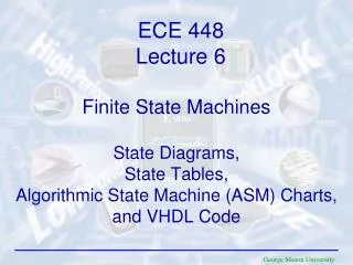
TP4: State Machine Design Pattern. Definition Infrastructure Transition Code Conclusion. State Machines.

E N D
TP4: State Machine Design Pattern Definition Infrastructure Transition Code Conclusion
State Machines • You use the state machine design pattern to implement algorithms that can be explicitly described by a state diagram or flow chart. A state machine consists of a set of states and a transition function that maps to the next state.
State Machine Infrastructure • While Loop: The follow of the state transition diagram is implemented by the while loop. The while loop allows to execute the various states continually. • Case Structure: the individual states are represented by cases in the case structure. It contains a case for each state and the code to execute for each state. • Shift Register: A shift register on the while loop keeps track of the current state to the Case structure input • State Functionality Code: it is used to implement the function of the state(it is located in the case structure). • Transition Code: the transition code determines the next state in the sequence, we usually use the “enum” constant to determine the next state. 1 2 3 5 4
Controlling the State Machine You use enumerated type constants as case selectors to control the initialization and transition of state machines. The most common obstacle when implementing state machines with enumerated type constants is that if a user attempts to add or delete a state from the enumerated type constant, the remaining wires connected to the copies of this enumerated type constant break. One solution to this problem is to type define the enumerated constant. Creating a type defined enumerated type constant causes all the enumerated type constant copies to automatically update if you add or remove a state. Enumerated Type Constant
State Machines A state machine relies on user input or in-state calculation to determine which state to go to next. Many applications require an initialization state and a default state, where many different actions can be performed. State machines are commonly used to create user interfaces where different user actions send the user interface into different processing segments. Each processing segment acts as a state in the state machine. Each segment leads to another segment for further processing or waits for another user action. Click on each button to see how different actions can lead to different states!
Transition Code • There are several common design patterns used to develop the transition code. You choose the transition code design pattern based on the number of states you need to transition between: • Transitioning to another state (Default Transition) • Transition between two possible states • Transition among two or more possible states
Default Transition • For the default transition, no code is needed to determine the next state, as there is only one possible choice.
Transition Between Two States • There are several patterns commonly used to accomplish transition between two states. This method (in the figure) works well if you know that the individual state always moves between two states. But, If you need to modify the state to transition among more than two states, this solution would not work and would require a major modification of the transition. code.
Transition Among Two or More States You can create a more scalable architecture by using one of the following methods for transition among multiple states: • Case Structure: Each case in a Case structure corresponds to an item in the enumerated type control, making it easy to read and understand the code. A Case structure is also scalable and you can add more transitions to a particular state by adding more cases to the Case structure. However, due to the nature of the Case structure, you cannot see the complete functionality of the transition code at a glance.
Transition Among Two or More States:Case Structure Explication Case1 Case2 Case3 This case structure means, In the “Analyzer Case”: If the string “Analysis”= “One” the next state will be “Start” If the string “Analysis”=“Two” the next state will be “Analyzer” If the string “Analysis”=“Three” the nest state will be “Error Handler.
Transition Among Two or More States 2. Transition Array: If you need more of the code to be visible than a Case structure allows, you can create a transition array for all the transitions that can take place in the transition code for a state.
State Machine: Conclusion • A state machine in LabVIEWconsists of a While Loop, a Case structure, a type defined enum constant and a shift register: • Each state of the state machine is a separate case in the Case structure. You place VIs and other code that the state should execute within the appropriate case. • A shift register stores the state (indicated by the enum constant)that should execute upon the next iteration of the loop. The next state will be either Shut Down or Idle
State Machine: Conclusion • For the displayed VI, the possible states are Startup, Idle, Event 1, Event 2, and Shutdown. An enumerated constant stores the states. Each state has its own case in the Case structure. The outcome of one case determines the case that next executes. The shift register stores a value that determines which case runs next.
State Machine Design Pattern • An advantage of the state machine architecture is that each case determines the next state, unlike Sequence structures that cannot skip a frame. • The state machine design can make the block diagram much smaller, and therefore easier to read and debug. • A disadvantage of the state machine design pattern is that it makes it possible to skip states. If two states in the structure are called at the same time, this model handles only one state, and the other state does not execute.