Download
1 / 35
360 likes | 572 Views
P. P'. P. Introduction. Stress: When some external system of forces act on a body, the internal forces are set up at various sections of the body, which resist the external forces. This internal forces per unit area at any section of body is known as stress. P'.

E N D
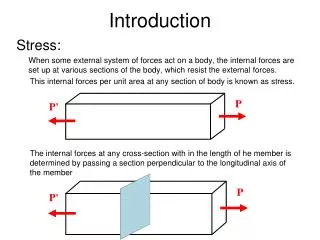
P P' P Introduction Stress: When some external system of forces act on a body, the internal forces are set up at various sections of the body, which resist the external forces. This internal forces per unit area at any section of body is known as stress. P' The internal forces at any cross-section with in the length of he member is determined by passing a section perpendicular to the longitudinal axis of the member
σ = P ' /A P '
Aθ A0 F θ P P' P P' V • Shear Stress: When a body is subjected to two equal & opposite forces, as a result of which the body tends to shear off the section, the stress induced is called Shear Stress.
P Uniaxial Stress system (Stress due to axial loading) Prismatic member is subjected to an axial load P as shown in Fig. 1 P' Figure No. 1
P P' The internal forces at any cross-section with in the length of he member is determined by passing a section perpendicular to the longitudinal axis of the member and set it to equilibrium as shown in Fig. 2. Figure No. 2
σ = P/A P The internal force N at the cross-section of intrest is equal in magnitude to the applied load P. The stress also acts normal to the cut section as shown in Fig. 3 and is equal to Figure No. 3
P P' θ Where σ = Normal stress P = Axial force A = Area of cross-section perpendicular to longitudinal axis However there is no shear stress. Now if we consider a section which is inclined at an angle θ w.r.t. horizontal or longitudinal axis (shown in Fig. 4). Figure No. 4
Aθ A0 N θ P P' V Then the force P is decomposed into components N and V. (shown in Fig. 5) Figure No. 5 The force, N leads to system of normal stresses (σn) and force V leads to shear stresses () as shown in Fig. 6
σ θ P' Figure No. 6 Following expressions are obtained by applying the equation of equilibrium along n and t axis as shown in Fig. 7. t-axis n-axis N θ P θ v θ t-axis Psinθ Pcosθ n-axis Figure No. 7
θ A A' Figure No. 8 So substituting value of A' in (2).
The above formulae may also be expressed in terms of double angles.
σ θ Graphical representation of these is shown in figure (9). Figure No. 9
1 0 -½
It would prove helpful in visualizing more readily the variation in normal and shearing stress with respect to each other and with angle θ. The graph shows that normal stresses are maximum at 0o and 180o and minimum at 90o and 270o. It can be noted that where normal stresses are maximum or minimum the shear stress is always zero. These maximum or minimum normal stresses are called Principal stresses and the Plane on which they act (Plane of zero shear stress) are known as Principal Planes. Also it can be noted that maximum values of shear stress occurs when θ is 45o or 135o and also that
Therefore maximum stresses are given by the following expression. The maximum and minimum values of σ and can also be determined by using calculus i.e. by differentiating them with θ and equating it zero.
Importance of Tension Test These observations lead us to consider more carefully the question of the strength of a bar in simple tension. If the bar is made of a material that is much weaker in shear than it is in cohesion, it may happen that failure will take place due to relative slipping between two parts of the bar along a 45°- plane where the shear stress is a maximum, rather than due to direct rupture across a normal section where the normal stress is a maximum. For example, a short wood post loaded in axial compression, as shown in Fig. 2.2a, may actually fail by shearing along a jagged plane inclined roughly by 45° to the axis of the post. In such case, we may still specify the value of P/A at which this failure occurs
as the ultimate strength of the wood in compression, even though the failure is not a true compression failure of the material. Similarly, during a tensile test of a flat bar of low-carbon steel with polished surfaces, it is possible to observe a very interesting phenomenon. At a certain value of the tensile stress σ= P/A visible slip bands approximately inclined by 45° to the axis of the bar will appear on the flat sides of the specimen as shown in Fig. 2.2b. These lines, called Lueders' lines, indicate that the material is failing in shear, even though the bar is being loaded in simple tension. This relative sliding along 45°-planes causes the specimen to elongate axially, and after unloading it will not return to its original length. Such apparent stretching of the bar due to this slip phenomenon is called plastic
yielding. Again, the axial tensile stress σy.p. = P/A at which this occurs may be designated as the yield stress in tension, even though the failure is not a true tension failure of the material. These matters will be discussed further in the next article. Laboratory experiments indicate that both shearing and normal stress under axial loading are important since a brittle material loaded in tension will fail in tension on transverse plane whereas a ductile material loaded in tension will fail in shear on the 45o plane.
Sign convention Formulas (2.1), derived for the case of axial tension, can be used also for axial compression, simply by changing the sign of P/A. We then obtain negative values for both the normal stress σnand the shear stress. The complete state of stress on a thin element between two parallel oblique sections for axial tension and axial compression are compared in Fig. 2.3. The directions of these stresses associated with axial tension (Fig. 2.3a) will be considered as positive; those associated with axial compression (Fig. 2.3b), as negative. Thus σnis positive when it is a tensile stress and negative when it is a compressive stress. By reference to Fig. 2.3, the rule for
sign of shear stress will be as follows: The shear stress on any face of the element will be considered positive when it has a clockwise moment with respect to a center inside the element (Fig. 2.3a). If the moment is counterclockwise with respect to a center inside the element, the shear stress is negative. Stated in a different way, the shear stress on any surface of a body will be considered to be of positive sign if it points in a direction corresponding to clockwise rotation about a center inside the body, otherwise of negative sign. Several examples of both positive and negative shear stress are shown in Fig. 2.4. These sign conventions, while arbitrary, must nonetheless be carefully observed to avoid confusion. At this point, we shall adopt a sign convention for these
stresses: If the stress points in a direction that corresponds to a clockwise rotation, the stress is positive; a negative shear stress is associated with counterclockwise rotation. As previously mentioned, the normal stresses are considered positive if there is a tensile load acting on that face; it is negative for a compressive load. Referring to Figure 1-20, stress xy is, according to our convention, positive, yx is negative, σ1 and σ2 are positive.
Complementary Stress: Returning to the case of a bar in axial tension, let us consider now the stresses on an oblique section p' q' at right angles to the section pq, as shown in Fig. 2.5. To obtain the stresses σ'n and 'on this section, we need
only to replace θ, by 90° + θin eqs. (2.1). Then remembering that sin (90° + θ)= cos θ " while cos(90° + θ)= - sin θthis gives These stresses on the plane p' q' act as shown in Fig. 2.5b. The complete set of stresses given by eqs. (2.1) and (2.1') are called complementary stresses because they occur on mutually perpendicular planes. Comparing the two sets of formulas, we observe that
Thus the sum of normal stresses σnand σ'n on any two mutually perpendicular sections of a bar in axial tension is constant and equal to P / A, the normal stress on the normal section mn. Also, complementary shear stresses are always equal in magnitude but opposite in sign.
Alternative The equality of complementary shear stresses such as and 'on the faces of a rectangular element (Fig. 2.6) also can be established from the equilibrium conditions of the element itself, as follows: Let dz denote the thickness of the element normal to the plane of the paper and ds, ds', the lengths of its edges. Then the areas on which and ' act will be, respectively, dsdz and ds'dz. Multiplying the shear stresses by the areas on which they act, we obtain two counteracting couples, the moments of which must balance each other. Thus (dsdz)× ds' = '(ds'dz) × ds,
from which = ', where ' has already been represented as negative in Fig. 2.6. Fig. 2.6


