Download
1 / 26
260 likes | 356 Views
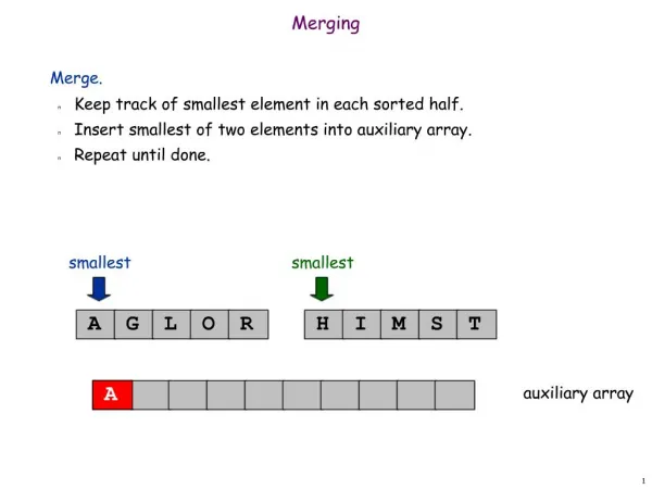
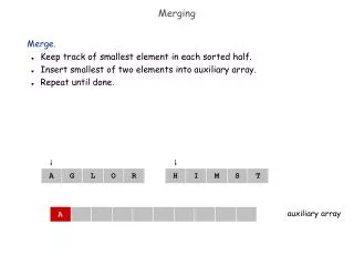
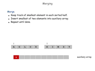
Pixel Hit Merging, Grouping etc. Jan. 2005. Outline. Grouping adjacent hits in same column saves data volume by factor of 1.5-2, as good as BCO ordering. Hit grouping needs no FIFO, it is a lot simpler than BCO ordering.

E N D
Pixel Hit Merging, Grouping etc. Jan. 2005
Outline • Grouping adjacent hits in same column saves data volume by factor of 1.5-2, as good as BCO ordering. • Hit grouping needs no FIFO, it is a lot simpler than BCO ordering. • Reduced data volume requires smaller buffer while doing BCO ordering and one-turn-per-highway scheme. • Keep an eye open on instantaneous rate: • BCO ordering will increase instantaneous rate to L1 trigger. • Hit grouping will not. • Merging 72 channels together in PDCB needs some thought.
X X X 0 0 Invalid coding: 1 0 1 1 X Sync24 Status 000 1 Input of PDCB b23 b22 b21 b20 b19 b18 b17 b16 b15 b14 b13 b12 b11 b10 b09 b08 b07 b06 b05 b04 b03 b02 b01 b00 Hit24 Row Column BCO(7:0) ADC 1 DCC et al Added in PDCB: Module # Chip # Turn # (Expanded BCO)
b15 b14 b13 b12 b11 b10 b09 b08 b07 b06 b05 b04 b03 b02 b01 b00 Input to L1 Trigger (Pack 4 ADC Using 13 bits) Idle: 00 =7 1 0 1 1 1 BCO Word: BCO(7:0) Tn(1:0) 0 1 0 1 1 0 Column Word: Module # Row Column ADC Word: ADC3 ADC2 ADC1 ADC0 Chip # Hits Status, Stn, hp. headers: Status etc. 0-6 1 0 1 1 1 Timing related info/headers: Timing Info etc. 0-3 1 1 0 1 1 0 Column X X X 0 0 Invalid Column coding: 1 0 1 1 X
RAM RAM RAM RAM FPGA FPGA FPGA FPGA RAM RAM RAM RAM TSO Module: Receiving Data from PDCB Buff PTSM FPGA VME P1 Buff Buff Optical Receiver P2 Inputs from 3 PDCB’s To be merged to 32-bit RAM
Merging in TSO FPGA ADC WordA2 ADC WordB2 ADC WordC2 Column WordA2 Column WordB2 Column WordC2 BCO WordA2 BCO WordB2 BCO WordC2 3 Clock (125 MHz) cycles ADC WordA1 ADC WordB1 ADC WordC1 Column WordA1 Column WordB1 Column WordC1 BCO WordA1 BCO WordB1 BCO WordC1 ADC WordC2 Column WordC2 BCO WordC2 ADC WordB2 Column WordB2 BCO WordB2 ADC WordA2 Column WordA2 BCO WordA2 3 Clock (125 MHz) cycles ADC WordC1 Column WordC1 BCO WordC1 ADC WordB1 Column WordB1 BCO WordB1 ADC WordA1 Column WordA1 BCO WordA1 Address to RAM Data (32-bit) to RAM
b15 b14 b13 b12 b11 b10 b09 b08 b07 b06 b05 b04 b03 b02 b01 b00 How to Pack 4 ADC Using 13 bits • There are 9 states for a sensor: not hit or ADC = 0-7. • 4 ADC’s can not be packed in 12 bits, can be packed in 14 bits (4x3 + 2 bits # of hits), but we have only 13 bits. • In theory, 13 bits can pack 4 items with 10 states each. So 4 ADC with 9 states each can be packed simply. • There are several ways to pack the 4 hits. ADC3 ADC2 ADC1 ADC0 Chip # Hits 1 ADC3 ADC2 ADC1 ADC0 Chip # 0 1 1 ADC2 ADC1 ADC0 Chip # 0 1 0 ADC1 ADC0 Chip # 0 0 1 ADC0 Chip # ADC3 ADC2 ADC1 ADC0 Chip # M3 M2 M1 M0 1 ADC3 ADC2 ADC1 ADC0 Chip # 0 1 1 1 ADC2 ADC1 ADC0 Chip # 0 0 1 1 ADC1 ADC0 Chip # 0 0 0 1 ADC0 Chip #
Pixel Hit Grouping Module # Chip # Row1 Column1 BCO1 ADC0 1 Module # Chip # Row1+1 Column1 BCO1 ADC1 1 Module # Chip # Row2 Column2 BCO2 ADC0 1 Module # Chip # Row2+1 Column2 BCO2 ADC1 1 Module # Chip # Row2+2 Column2 BCO2 ADC2 1 Module # Chip # Row2+3 Column2 BCO2 ADC3 1 Module # Chip # Row2+4 Column2 BCO2 ADC4 1 • Payload for one hit: • 4+3+7+5+8+3=30 bits • Group of 2: • 64/48=1.3 • Group of 3: • 96/48=2 • Group of 4: • 128/48=2.6 • Group of 2.5: • Data volume saving: 1.5 BCO1 Tn(1:0) 0 1 0 1 1 0 Module # Row1 Column1 0 1 0 ADC1 ADC0 Chip # BCO2 Tn(1:0) 0 1 0 1 1 0 Module # Row2 Column2 1 ADC3 ADC2 ADC1 ADC0 Chip # BCO2 Tn(1:0) 0 1 0 1 1 0 Module # Row2+4 Column2 0 0 1 ADC4 Chip #
Hit Group Composer (3-Hit Version) Row2 Row1 Row0 Row (7 bits) Row (7 bits) Col2 Col1 Col0 Col (5 bits) Col (5 bits) BCO2 BCO1 BCO0 BCO (8 bits) BCO (8 bits) ADC2 ADC1 ADC0 ADC (3 bits) ADC0,1,2 (9 bits) (BCO1==BCO0) GT_1_hit (Col1==Col0) (Row1==(Row0+1)) (!Used0) Eq_3_hits (BCO2==BCO1) (Col2==Col1) (Row2==(Row1+1)) Used0 Valid About 120 Logic Cells Used1
Not Affordable:One Hit Group Composer/Channel: Shift Register Hold Register Hit Group Composer Ch. 0 Phase Detect Frame Detect Hit Group Composer Ch. 1 Phase Detect Frame Detect FIFO Hit Group Composer Ch. 23 Phase Detect Frame Detect 120 Logic Cells each. 72 Ch: 8640 LC (32% xc3s1500)
Not Affordable:Even Just Registers and MUX Shift Register Hold Register Ch. 0 Phase Detect Frame Detect Ch. 1 Phase Detect Frame Detect Hit Group Composer FIFO 120 Logic Cells each. 72 Ch: 3x120=360 LC: OK But need to keep track of the “next hits”. Ch. 23 Phase Detect Frame Detect 72 Logic Cells / channel 72 Ch: 5184 LC (19% xc3s1500)
Delay Lines Barrel Shifter Delay Lines Ch. 0 Phase Detect Frame Detect Bit 23 Ch. 1 Phase Detect Frame Detect Hit Group Composer FIFO Ch. 23 Phase Detect Frame Detect Bit 0 ~160 Logic Cells / 24 channel 72 Ch: ~500 LC (2% xc3s1500) XAP149
Hit Group Composer Shift Reg. 24 Shift Reg. 24 Row, Col, BCO Row, Col, BCO ADC0 ADC ADC1 ADC2 Hit Grouping Logic Hits Valid Used Word Pipe Used Word Pipe
Hit Group Composer Hit Group Composer Hit Group Composer FIFO FIFO FIFO FIFO FIFO FIFO FIFO FIFO FIFO FIFO FIFO Ch. 0 Ch. 1 Ch. 23 Ch. 24 Ch. 47 Ch. 48 Ch. 71
Supporting Slides • Details are shown in next a few slides.
1 0000001 0 Station R/L View 1 0000010 0 Chip Module Bit assignments (From DCC) Pixel hit data: Some header records: BCO header: Half plane header: Chip header: 0 Row (7-bits) Col (5-bits) ADC 1 0000000 BCO – high order BCO BCO
0 0 0 Row (7-bits) Row+1 Row+2 Col (5-bits) Col (5-bits) Col (5-bits) ADC2 ADC0 ADC1 1 0000001 0 Station R/L View 1 0000010 0 Chip Module Same Column Groups BCO header: Half plane header: Chip header: Pixel Data 1 0000000 BCO – high order BCO BCO
b15 b14 b13 b12 b11 b10 b09 b08 b07 b06 b05 b04 b03 b02 b01 b00 Input to L1 Trigger (Simplified from Doc 3342) Idle: 00 =7 1 0 1 1 1 BCO & Turn: BCO(7:0) Tn(1:0) 0 1 0 1 1 0 Data word 0: Module # Row Column Data word 1 (repeat?): ADC2 ADC1 ADC0 Hits Chip # 0 0 Status, Stn, hp. headers: Status etc. 0-6 1 0 1 1 1 Timing related info/headers: Timing Info etc. 0-3 1 1 0 1 1 0 Column X X X 0 0 Invalid Column coding: 1 0 1 1 X
Pixel Hit Grouping Module # Chip # Row1 Column1 BCO1 ADC0 1 Module # Chip # Row1+1 Column1 BCO1 ADC1 1 Module # Chip # Row2 Column2 BCO2 ADC0 1 Module # Chip # Row2+1 Column2 BCO2 ADC1 1 Module # Chip # Row2+2 Column2 BCO2 ADC2 1 Module # Chip # Row2+3 Column2 BCO2 ADC3 1 Module # Chip # Row2+4 Column2 BCO2 ADC4 1 • Payload for one hit: • 4+3+7+5+8+3=30 bits • Group of 2: • 64/48=1.3 • Group of 3: • 96/48=2 • Group of 4: • 128/96=1.3 • Group of 2.5: • Data volume saving: 1.5 BCO1 Tn(1:0) 0 1 0 1 1 0 Module # Row1 Column1 ADC1 ADC0 Hits=2 Chip # 0 0 BCO2 Tn(1:0) 0 1 0 1 1 0 Module # Row2 Column2 ADC2 ADC1 ADC0 Hits=3 Chip # 0 0 BCO2 Tn(1:0) 0 1 0 1 1 0 Module # Row2+3 Column2 ADC4 ADC3 Hits=2 Chip # 0 0
BCO Header, Column Header BCO1 Tn(1:0) 0 1 0 1 1 0 • The types of the words can be recognized from lower 5 bits. So they can be used either as data or header. • If the BCO is sorted by PDCB, the BCO word can be used as header. • The Column word can also be used as a header. However, it is not recommended since the instantaneous rate will be too high. • The easiest is three-word fix-size data stream as shown in previous slide. Module # Row1 Column1 ADC1 ADC0 Hits=2 Chip # 0 0 Module # Row2 Column2 ADC2 ADC1 ADC0 Hits=3 Chip # 0 0 BCO1 Tn(1:0) 0 1 0 1 1 0 Module # Row1 Column1 ADC1 ADC0 Hits=2 Chip # 0 0 Module # Row2 Column2 ADC2 ADC1 ADC0 Hits=3 Chip # 0 0 ADC4 ADC3 Hits=2 Chip # 0 0
TSO TSO TSO TSO TSO P2 PP PP PP PP PP PP PP PP The TSO and PP Stage (Half Highway) From PDCB, 5x12 fibers, 2.5 Gb/s/fiber To Segment Trackers, 8x8 cables, 1.5 Gb/s/cable
Supported Configuration:5x8, Half Highway TSO Modules PP Modules TSO Modules PP Modules CPU P1 P2
The TSO Module • Serial data from optical receiver are sent to FPGA devices at 2.5 Gb/s per channel. • Time stamp ordering is done in FPGA and RAM. • Time stamp ordered data are sent to the backplane connector at 300 – 500 Mb/s per pair. • The data are sent to the PP modules via backplane. Buff FPGA VME Buff RAM RAM Buff FPGA FPGA RAM RAM Optical Rec ZL60102 RAM RAM FPGA FPGA RAM RAM
RAM RAM RAM RAM FPGA FPGA FPGA FPGA RAM RAM RAM RAM TSO Module Buff PTSM FPGA VME P1 Buff Buff Optical Receiver P2
7 7 7 7 7 7 7 7 7 7 7 7 7 7 7 7 7 6 6 6 6 6 6 6 6 6 6 6 6 6 6 6 6 6 5 5 5 5 5 5 5 5 5 5 5 5 5 5 5 5 5 4 4 4 4 4 4 4 4 4 4 4 4 4 4 4 4 4 3 3 3 3 3 3 3 3 3 3 3 3 3 3 3 3 3 2 2 2 2 2 2 2 2 2 2 2 2 2 2 2 2 2 1 1 1 1 1 1 1 1 1 1 1 1 1 1 1 1 1 0 0 0 0 0 0 0 0 0 0 0 0 0 0 0 0 0 Delay Lines Delay Lines Barrel Shifter Hit Group Composer FIFO 6 5 4 3 2 1 0 5 4 3 2 1 0 7 4 3 2 1 0 7 6 3 2 1 0 7 6 5 2 1 0 7 6 5 4 1 0 7 6 5 4 3 0 7 6 5 4 3 2 7 6 5 4 3 2 1 1 2 3 4 5 6 7 7 7 7 7 7 7 7 7 7 7 7 7 7 7 7 7 7 7 7 7 7 7 7 6 6 6 6 6 6 6 6 6 6 6 6 6 6 6 6 6 6 6 6 6 6 6 5 5 5 5 5 5 5 5 5 5 5 5 5 5 5 5 5 5 5 5 5 5 5 4 4 4 4 4 4 4 4 4 4 4 4 4 4 4 4 4 4 4 4 4 4 4 3 3 3 3 3 3 3 3 3 3 3 3 3 3 3 3 3 3 3 3 3 3 3 2 2 2 2 2 2 2 2 2 2 2 2 2 2 2 2 2 2 2 2 2 2 2 1 1 1 1 1 1 1 1 1 1 1 1 1 1 1 1 1 1 1 1 1 1 1 0 0 0 0 0 0 0 0 0 0 0 0 0 0 0 0 0 0 0 0 0 0 0