Download
1 / 54
740 likes | 1.3k Views
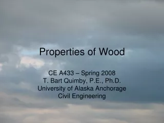
Properties of Wood. CE A433 – Spring 2008 T. Bart Quimby, P.E., Ph.D. University of Alaska Anchorage Civil Engineering. Cellular Makeup. Cells are elongated, tube like cells Cell walls are made of cellulose Cells are bound together by lignin.

E N D
Properties of Wood CE A433 – Spring 2008 T. Bart Quimby, P.E., Ph.D. University of Alaska Anchorage Civil Engineering
Cellular Makeup • Cells are elongated, tube like cells • Cell walls are made of cellulose • Cells are bound together by lignin http://concise.britannica.com/ebc/art-66141/Cross-section-of-a-tree-trunk
Effect of Cell Structure • Since the cells are elongated, the wood has different strength properties when stress is transverse or parallel to the cell longitudinal axis. • Shrinkage properties are also different in each direction.
Grain • Grain runs along the trunk. • Grain size is non uniform Grain Direction
Principle Directions • “With the Grain” = Longitudinal • “Cross Grain” or “Perpendicular to Grain” = Radial or Tangential • Strength and Shrinkage Properties are DIFFERENT IN EACH DIRECTION Radial Tangential Longitudinal http://concise.britannica.com/ebc/art-66141/Cross-section-of-a-tree-trunk
Moisture Content & Shrinkage MC = (moist wt – oven dry wt)/ (oven dry weight) x 100 • Living trees may have MC up to 200%. • Lumber in service has MC less than 20% • The loss of moisture results in wood shrinkage • Shrinkage is most pronounced perpendicular to grain • Moisture is found within the wood cell cavities (free water) and the cell walls (bound water)
More Moisture • Fiber Saturation Point (FSP): The MC where all the free water is lost, leaving only the bound water. There is no shrinkage when the MC is above the FSP • Volume changes take place as the MC varies below the FSP. • Typically, MC continues to decrease after both manufacturing and installation. • Equilibrium Moisture Content (EMC): The in service moisture content • This can vary with occupancy and/or season Manufacture Installation
Shrinkage Example • 5 Story Condo in Juneau, AK • It rained all but 3 days during the 4-5 weeks of framing. • In the first year after construction there was considerable shrinkage
Imperfections in Wood Knots http://www.vermonttimberworks.com/images/shake.jpg
Members Cut from a Log Cross Grain • Perpendicular to grain direction may be either tangential, radial, or a combination of each Cross Grain Cross Grain http://web.utk.edu/~grissino/images/zuni%20doug-fir.jpg
Sawn Lumber Visual Grading • Rules agencies establish grading rules based on observed wood quality • Inspector’s visually grade and mark each piece as it is manufactured
Pressure Treated Wood • Wood is often chemically treated to increase it’s durability • Minimizes decay and mold • Discourages insect infestation • Fire treatments also available • Moist, dark (or nearly dark) locations with minimal air circulation are prime locations for decay and mold • High moisture conditions that are variable are also problematic
Standard Sizes for Sawn Lumber • NDS Supplement Section 3, Table 1B • Nominal Sizes are larger than the actual sizes! • Check out the sizes! Not all are readily available • Some available sizes: • 2x2 to 2x12 • 4x4 to 4x12 • 6x6 to 6x12
Sawn Lumber Size Classifications • See text pg 4.30 • Structural Joists and Plank (SJ&P) • 2 to 4 inches thick • 2 inches and wider • Beams & Stringers (B&S) • 5 inches & thicker • Width > thickness + 2 inches • Posts & Timbers (P&T) • 5 inches & thicker • Width <= thickness + 2 inches
Glue Laminated Timbers • Laminations can be strategically used to make efficient use of the best materials. • Members can be fabricated for particular uses • Larger, Longer, & Curved sections are possible http://www.lamisellbeams.com/images/cover-image/lamisell-image03c-shadow04.jpg
Glulams Designed as Beams • Best material on outer faces • Butt splice in compression zone • Scarf splice in tension region
Glulams Designed as Columns • Materials more uniform • Butt joints can be used throughout
Glulam Standard Sizes • See NDS Supplement Table 1C • Common Widths for Western Species GL • 3.1/8”, 5.1/8”, 6.3/4”, 8.3/4”, 10.3/4” • Common depths: • 6” and larger, in 1.1/2” increments http://www.woodnet.org.uk/wec/images/gluelam2.jpg
The National Design Specification • The “model code” for timber design in the US • The NDS Specification tells us what we can do with timber • The NDS Supplement provides material data for the various types of timber
Basic Design Inequality • As with all structural codes: Req’d Strength < Available Capacity • In the NDS this takes the general form: f < F’ or U <fN • Where: • f = stress caused by internal forces • F’ = adjusted design stress = F * modifiers • F = Reference design stresses • U = the LRFD factored internal force • N = nominal capacity = F’ * (Section Property)
Sawn Lumber Reference Values • NDS Supplement Table 4A
Sawn LumberReference Values • NDS Supplement Table 4D
Glulam Reference Values • NDS Supplement Table 5A
Glulam Reference Values • NDS Supplement Table 5B
Sawn Lumber Design Values • NDS Table 4.3.1
Glulam Design Values • NDS Table 5.3.1
CM: Wet Service Factor • Applies to all reference values • Applies to both Sawn Lumber and Glulams • Specified in EACH NDS Supplement Reference Value Table • This factor generally reduces strengths for wood that is used in a high moisture environment (EMC > 19%)
Ct: Temperature Factor • Applies to all reference values • Use for timber used in environments with sustained temperatures up to 150 deg F • NDS 4.3.4 for Sawn Lumber & NDS 5.3.4 for Glulams • References NDS Table 2.2.3
CL: Beam Stability Factor • Applies only to bending stress, Fb • Applies to both Sawn Lumber and Glulams • Found in NDS 3.3.3 • This factor accounts for instability in laterally unsupported beams (i.e. lateral torsional buckling) • Glulams: This factor is NOT simultaneously applied with the Volume Factor, CV • More on this factor when we cover beam design
More CL • See NDS Equation 3.3-6 • LTB is a function of both the laterally unbraced (buckling) length AND the variation in the moment diagram. • First check the slenderness ratio • RB must not exceed 50 • Then compute CL • Note that CL is a function of the beam size! • This means that you must know the beam size before computing this factor • When designing, this may lead to iterative computations
CF: Size Factor • Applies to Sawn Lumber Fb, Ft, and Fc bent about the strong axis • Found in NDS 4.3.6 • 4.3.6.1: For SJ&P see NDS Supplement Tables 4A and 4B • 4.3.6.2: For B&S with d > 12”, CF = (12/d)1/9 • 4.3.6.3: For beams of circular cross section • The reference values are normalized to a 12” deep member. This factor accounts for the difference.
Cfu: Flat Use Factor • Applies only to Fb for both Sawn Lumber and Glulams when the member is bent about it’s minor axis. • Found in NDS 4.3.7 and 5.3.7 • For Sawn Lumber, values for Cfu are found in the NDS Supplement Tables 4A, 4B, 4C, and 4F • For Glulams, values for Cfu are found in the NDS Supplement Tables 5A, 5B, 5C, and 5D
Ci: Incising Factor • Applies to all reference values for Sawn Lumber. • Found in NDS 4.3.8 • Accounts for damage to member due to incisions made for chemical pressure treatment.
Cr: Repetitive Use Factor • Applies to Sawn Lumber Fb • Found in NDS 4.3.9 • Read criteria in NDS • Intended to account for the community effort of a repetitive series of bending members such as joists, rafters, studs, etc.
Cp: Column Stability Factor • Applies to Fc for both Sawn Lumber and Glulams • Found in NDS 3.7 via 4.3.10 and 5.3.9 • This factor accounts for column stability as a function of slenderness. • There will be more on this factor when column design is discussed.
CT: Buckling Stiffness Factor • Applies to Emin for Sawn Lumber, which has an impact on Cp • Found in NDS 4.4.2 via 4.3.11 • Only applies to truss top chord members, subject to combined bending and axial compression, and made of 2x4 or smaller sections that meet certain criteria.
Cb: Bearing Area Factor • Applies to Fcp for both Sawn Lumber and Glulams • Found in NDS 3.10.4 via 4.3.12 and 5.3.10 • Accounts for increased strength of bearing areas which are, in part, aided by adjacent wood. • More on this one when we cover beams.
CD: Load Duration Factor • ASD ONLY!!!! • Applies to Fb, Ft, Fv, Fc for both Sawn Lumber and Glulams. Also applies to Frt for Glulams. • Found in NDS 2.3.2 via 4.3.2 and 5.3.2 • The value of CD is based on the actual shortest duration load in the load combination being considered. This has the unfortunate affect of making it very difficult to determine the controlling load combination!
Time Effects on Timber Strength • “Wood has the property of carrying substantially greater maximum loads for short durations than for long durations of loading.” NDS 2.3.2.1
Determining ControllingLoad Case • Consider ASD tensile limit state: Ta/A = ft< F’t = FtCDCMCt for ALL LOAD COMBINATIONS • CD is different for every considered ASCE 7 load combination • This makes it tough to see which Ta to use. • To determine the controlling load case divide both sides by CD (Ta/CD)/A = ft / CD< F’t / CD = FtCMCt • The load combination that gives the largest Ta/CD is the controlling load combination
Example • Consider a column subjected to the loads shown
Structural Elements with Multiple Load Sources • Each source has a different make up • Which ASD LC controls the design of the member? D, Lr, S, L D, L W, E
- Determine CD for each source and each combination. - Pick the controlling CD for the combination and apply to all loads in the combination.
f: Resistance Factor • LRFD Only!!!!! • Applies to all reference values except for E • Found in NDS Appendix N.3.2 via 4.3.15 and 5.3.13
KF: Format Conversion Factor • LRFD Only!!!!! • Applies to all reference values except E • Found in NDS Appendix N.3.1 via 4.3.14 and 5.3.12 • Need to know f to determine KF
l: Time Effect Factor • LRFD Only!!!!! • Applies to all reference values except E and Emin. • Found in NDS Appendix N.3.3 via 4.3.16 and 5.3.14 • This is the LRFD equivalent to CD. l accounts for time effects on strength. • l is easier to apply than CD since it’s value is specified by ASCE 7 LRFD load combination instead of by actual shortest duration load • Still need to divide load by l to find controlling cases
Example • Consider a column with the loads shown