Download
1 / 22
240 likes | 445 Views
CREATING THE DESIGN: THE LOGICAL VIEW. The Class Diagram. FROM USE-CASES TO CLASSES. The use-case diagram is the primary source from which the designer identifies the classes of the system being developed There are 3 types of classes represented in use cases Entity Classes

E N D
CREATING THE DESIGN: THE LOGICAL VIEW The Class Diagram
FROM USE-CASES TO CLASSES • The use-case diagram is the primary source from which the designer identifies the classes of the system being developed • There are 3 types of classes represented in use cases • Entity Classes • Boundary Classes and • Control Classes
FROM USE-CASES TO CLASSES • ENTITY CLASSES: • Model the information and associated behavior that is generally long lived (persistent) • Used to represent real-world entities or system specific entities • They are • independent of their surroundings and • application independent • Entity classes typically are those classes needed by a system to accomplish some responsibility (thus the best place to identify them is in the Flow-of-Events document of each use case)
FROM USE-CASES TO CLASSES BOUNDARY CLASSES: • These are interface classes • Handle the communication between the system surroundings and the inside of the system • Provide interface to a user or another system • Located by examining each physical actor/scenario pair
FROM USE-CASES TO CLASSES CONTROL CLASSES • These model sequencing behavior specific to one or more use cases • They coordinate the events needed to realize the behavior specified in the use case • Thus a control class “runs” or “executes” the use case • They are application dependent
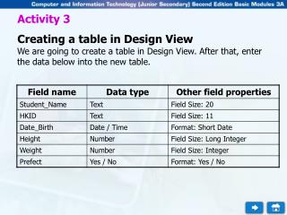
FROM USE-CASES TO CLASSES CREATING AND DOCUMENTING CLASSES • To create a class in rational rose: • Right click on the logical view in the browser • Select the new:class menu choice • Name the created class appropriately • Right click on the class to make the shortcut menu visible • Select the Open Specification menu choice • Select the general Tab • Click the arrow in the Stereotype field to make the drop-down menu appear and select the desired stereotype (entity, control, or boundary) • Click in the documentation window the formally define the class • Click the OK button to close the specification
FINDING ENTITY CLASSES: The OO Approach • The OBJECT MODEL, also termed the CLASS DIAGRAM contains the key classes in a system and elaborated the attributes and behaviors of each class • Classes define the structure and behaviors (methods) of a set of objects • The structure is represented as attributes (data values) and associations (relationships between classes) • Thus all entity classes will be modeled on the Object Model
FINDING ENTITY CLASSES: The OO Approach • To identify the entity classes that go into the object model: • Read each flow-of-events document for each use case and identify the Nouns therein • Determine if these nouns represent entities for which information will be stored in the system’s database • Each of these entities becomes a class • For each class identify the pieces of information that will be used to represent it (describe it) within the system. These are its attributes.
MODELING ENTITY CLASSES: The OO Approach • Create each class as elaborated earlier • To add attributes to each class • right-click on a class in the diagram window • Select the New attributes menu option on the pop-up menu that appears • Type in the name of the attribute • right-click on the class, select the attributes tab, then double click on the newly created attribute • Key in the properties of this attribute • Relate the classes together using lines and appropriate multiplicity symbols (next slide)
MODELING ENTITY CLASSES: The OO Approach • A relationship is an association between any two classes. • Common types of relationships are: • Association relationship: between two classes that are dissimilar (e.g. student to course) • Aggregation: “is a part of” relationship • Generalization/Specialization: “is a” relationship • MULTIPLICITY refers to the degree of the relationship between two classes. • Common multiplicity levels are: • Zero, one or many • Thus giving : • Zero to one, zero to one or many, one to many, many to many, etc.
DEFINING CONTROL AND ENTITY CLASSES • About the best way to determine control and interface classes is to develop: • use case realizations • interaction models (sequence or collaboration diagrams)
DEFINING CONTROL AND ENTITY CLASSES USE CASE REALIZATIONS • Use case realization models are diagrams developed in the logical view • They identify the logical mappings of use cases to software components, modules, or program files • Use case realizations are drawn as dashed ovals and are normally given the same name as the use case in the use-case view • Traceability is visualized by adding the use-cases to the realization diagrams and connecting them to their realizations via stereotyped unidirectional associations • NB: design elements are used in the design use case realizations (e.g, interface objects, actions as messages, etc)
DEFINING CONTROL AND ENTITY CLASSES INTERACTION DIAGRAMS • Common interaction diagrams used in RUP are the sequence diagram and the collaboration diagram • From Sequence diagrams one can quickly identify: • boundary classes, • control classes, and • the messages that eventually become methods of the classes in the system
IDENTIFYING METHODS • Messages in the interaction diagrams typically are mapped to methods (operations) of the receiving class • however, there are some special cases where the message does not become an operation (method) • where the receiving class is a boundary class that is a place holder for a GUI type class, the message becomes a statement of the requirements for the GUI and is implemented as a GUI control (e.g. a button) • where the message is to or from an actor that represents a physical person, the message is a statement of human procedure and is therefore incorporated in the user manual • where the message is to or from an actor that represents an external system, a class is created to hold the protocol that is used to perform the communication with the external system
IDENTIFYING METHODS • Operations should be named in terms of the class performing the operation • operation names should not reflect the implementation of the operation • calculateNumberofStudents() : not correct • getNumberofStudents(): correct • Document each operation to capture all detail relating to it. I.e: • functionality performed by the operation • any input values needed • return values of the operation • the input and return values constitute the operation’s signature
IDENTIFYING METHODS • The signature of an operation may indicate a relationship • if the class for an argument of an operation or the return from an operation is a fundamental class such as a string, the relationship typically is not shown on the class diagram • for non-fundamental classes, e.g attributes or objects, the relationship is shown. • Relationships based on operation signatures are modeled as associations that may be refined into dependency relationships as the design matures.
DEFINING METHODS • A method definition describes the steps that a class performs to accomplish a particular operation • It has two parts - the header and the body • The header for a method consists of : • An access specifier: defines who can use the method • the type of value returned when the method is called (invoked) • The name of the method • A pair of parentheses used to hold information that is passed to the method • an optional list of parameters providing information that customizes the behavior of the method
DEFINING METHODS Method Header Access Specifier Return Type Method Name ( Arguments ) { Declaration Statements ; Method Calls ; Method body Expression Statements ; Flow of Control Statements ; }
DEFINING METHODS • The body of a method enumerates the: • Declaration statements: allow creation of local variables using primitives or objects • Method calls: invoke other methods • Expression statements: a combination of operands and operators that, when executed, produces a value • Flow of Control Statements:Statements that determine the order in which program logic gets executed (the thread through which the execution of a method flows)
EXAMPLE • IN CLASS DEMOSTRATION/EXAMPLE SYSTEMS PROJECT • The UNIVERSITY OF BUTERE (UBT) registration system is briefly described thus: You have been asked to streamline, improve, and automate the process of assigning professors to courses and the registration of students such that it takes advantage of prevailing web technologies for on-line real time, location independent access. The process begins by professors deciding on which courses they will teach for the semester. The Registrar’s office then enters the information into the computer system, allocating times, room, and student population restrictions to each course. A batch report is then printed for the professors to indicate which courses they will teach. A course catalogue is also printed for distribution to students. Students then select what courses they desire to take and indicate these by completing paper-based course advising forms. They then meet with an academic advisor who verifies their eligibility to take the selected courses, that the sections of the courses selected are still open, and that the schedule of selected courses does not clash. The typical student load is four courses. The advisor then approves the courses and completed the course registration forms for the student. These are then sent to the registrar who keys them into the registration system – thereby formally registering a student. If courses selected are not approved, the student has to select other courses and complete the course advising forms afresh. Most times students get their first choice, however, in those cases where there is a conflict, the advising office talks with the students to get additional choices. Once all students have been successfully registered, a hard copy of the students’ schedule is sent to the students for verification. Most student registrations are processed within a week, but some exceptional cases take up to two weeks to resolve. Once the initial registration period is over, professors receive a student roster for each class they are scheduled to teach.