Download
1 / 76
830 likes | 1.29k Views
Focused X-Ray Beams : Generation and Applications. G S Lodha Indus Synchrotrons Utilization Division RRCAT, Indore. Advances in Science, Engineering and Technology Colloquium TIFR, August 20, 2010. lodha@rrcat.gov.in. X-ray Interaction with Matter. source: Spring-8 web site.

E N D
Focused X-Ray Beams : Generation and Applications G S Lodha Indus Synchrotrons Utilization Division RRCAT, Indore Advances in Science, Engineering and Technology Colloquium TIFR, August 20, 2010 lodha@rrcat.gov.in
X-ray Interaction with Matter source: Spring-8 web site
Focused X-ray Beams W.C. Roentgen : Refractive index of all materials ≈ unity Difficult to make an x-ray lens. With the recent availability of extremely bright x-ray sources (synchrotron storage rings, x-ray free electron lasers, …), R&D efforts towards focusing x-rays to smaller and smaller size have become intense. At present it is possible to generate focused x-ray beam of <30 nm, using the reflection, diffraction and refraction phenomena in the x-ray region.
Optics for X-ray (~10 keV) • Complex refractive index: n=1-δ+iβ • Refraction is small: Re(n)=1-δ with δ=10-6 ….10-5 • Focal length: f=R/2 (n-1) = R/2δ • Absorption is high: absorption lengths 1μm … 10μm • Figure of merit: β/δ = 10-5 (Li,Be) …10-3 (C,Al,Si) …10-1 (Au,Pt,W) Dilemma • smaller f smaller R • more flux larger aperture larger R
Why focus x-ray to sub micron size? X-ray microscopy: Most materials are heterogeneous at length scale of micron to nm (transmission microscopy, scanning microscopy…). Increased flux: Higher sensitivity due to reduced background. Small samples or samples in different environment (pressure, temperature, magnetic field …)
General Terminology in X-Ray Optics • Magnification • Numerical Aperture • Resolution • Depth of focus • Astigmatism • Chromatic Aberration
Ideal focusing lens: Converts plane wave to a spherical wave, with the conservation of the coherence • In-coherent source Geometric Optics Refraction 1/F = (n-1) (1/Do + 1/Di) • Coherent source Wave Optics Refraction Phase shift along the optical path For generating x-ray micro/ nano focused beam M~10-2 to 10-4 in synchrotron beamline. Magnification: M=Di/Do
Numerical Aperture • Measure of light collection power NA= n Sin θmax NA ~ 0.5 (D/f) NA is very closely related to performance of the optics (e.g. depth of focus, diffraction limited resolution, flux etc.). Low NA is one of the major constraint for x-ray optics.
For high photon flux at the focus:High brightness and large numerical aperture • Focusing increases the angular spread. • Brightness: B= P/ (ΔAs . ΔΩs) P : radiated power; ΔAs :source area ; ΔΩs : source divergence The photon flux at the focus is ~ B. 2 . NA2. η is spot size and η is the efficiency of the optics. Thus the high photon flux at the focus requires high source brightness and large numerical aperture optics.
Rayleigh’s Criterion: Resolution Limit • Point sources are spatially coherent • Mutallyincoherent • Intensities add • Rayleigh criterion (26.5% dip) • Conclusion : With spatially coherent illumination, objects are “just resolavable” when source: D. Attwood
Depth of focus Where is a spot size source: Xradia
Astigmatism Horizontal and vertical focusing are separated at grazing incidence. fm = (R Sin θ)/2 fs= R/(2Sinθ) Synchrotron radiation sources Source Focus Reflection Crossed mirror pair (Kirkpatrick-Baez system) or or
Chromatic aberration Reflective Optics: Can focus pink beams using grazing incidence optics. Grazing angles can be higher by using x-ray multilayer reflector, but at the cost of limited energy Diffractive Optics : f ~ E , small NA Refractive Optics : f ~ E2
X-ray Micro focussingoptics • Reflective optics • Diffractive optics • Refractive optics
X-ray Reflectivity: Single and Multilayer Multilayer Large θ leads to larger acceptance or shorter mirror length. Spectral bandwidth ~ a few % Single Layer Total external reflection when θ<θc (a few mrad) c = √2 = λ√Z
X-ray Multilayer Optics Advantages • Layer thicknesses can be tailored • Can be deposited on figured surfaces
Reflective optics • Schwarzschild objective • Woltermicroscope • Capillary optics • Kirkpatrick-Baez mirrors
Schwarzschild objective • Near normal incidence with • multilayer coating (126 eV) • N.A. > 0.1 • Imaging microscope source: F. Cerrina (UW-Madison), J. Underwood (LBNL)
Wolter microscope • Use 2 coaxial conical mirrors with hyperbolic and elliptical profile • Imaging microscope • Difficult to polish for the right figures and roughness
Capillary optics • One-bounce capillary • Large working distance (cm) • Compact: may fit into space too • small for K-B • Nearly 100% transmission • N.A. ~ 2-4 mrad (¡Ü 2θc) • Difficult to make submicron spot • Multi- bounce condensing capillary • Easy to make with small • opening (submicron) • Short working distance (100 μm) • Low transmission source: D. Bilderback (Cornell)
Kirkpatrick-Baez mirrors • A horizontal and a vertical mirror arranged to have a common focus • Achromatic: can focus pink beam (but not with multilayer coating) • Can be used to produce ~ round focal spot • Very popular for focusing in the 1-10 μm • APS 85x90 nm2 ESRF 45 nm, Spring8 25x30 nm2 • (diffraction limit ~ 17 nm)
Diffractive optics • Fresnel zone plates (FZP) • Multilayer Laue Lens (MLL)
Fresnel zone plates (Phase ZP and Amplitude ZP) • Efficiency of an amplitude ZP with opaque zones ~ 10% • Efficiency of a phase ZP with π-phase shift ~ 40% Phase For a phase shift of
Fabrication Fresnel zone plates E Anderson, A Liddle, W Chao, D Olynick and B Harteneck (LBNL)
Hard X-ray ZP: recently available Δr = 24 nm, 300 nm thick, Aspect Ratio = 12.5 (Xradia) Aspect ratio > 100 is probably difficult to achieve with lithographic zone plates! W. Yun (Xradia)
Multilayer Laue Lens (MLL) For high aspect ratio Aspect ratio > 1000 (Δr = 5-10 nm, 10 μm thick) demonstrated Source : A. Macrander (APS)
Refractive optics • Compound refractive lens (CRL) Small aperture Small focusing strength Strong absorption E>20keV f = R/2N R radius (~200 m) N number of lenses (10 …300) real part of refractive index (10-5 to 10-6) 2R0 800 m -1000 m d 10 m -50 m Parabolic profile : No spherical aberration Source : Achen Univ., APL 74, 3924 (1999)
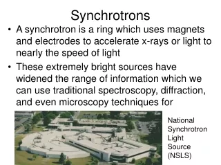
What is Synchrotron Radiation? Synchrotron radiation is emitted from an electron traveling at almost the speed of light (0.99999999C) and its path is bent by a magnetic field. It was first observed in a synchrotron in 1947. Thus the name "synchrotron radiation".
Generation of Synchrotron Radiation Synchrotron radiation is emitted at a bending magnet or at an insertion device. Corresponding to the weak and strong magnetic field, there are two types of insertion devices: an undulator and a wiggler.
General Properties of Synchrotron Radiation • Ultra-bright • Highly directional • Spectrally continuous (Bending Magnet /Wiggler) or quasi-monochromatic (Undulator) • Linearly or circularly polarized • Pulsed with controlled intervals • Temporally and spatially stable
Synchrotron Radiation(SR) Sources… America: 18 Asia: 25 Europe: 22 Oceania: 1 IV generation light sources under construction/ planning stage.
Creating SR light (3) Then they pass into the booster ring accelerated to c (4) And are finally transferred into the storage ring A typical Synchrotron source With BM and ID (1) Electrons are generated here (2) Initially accelerated in the LINAC
Building a Synchrotron Source… Synchrotron Magnets Beam physics LCW UHV Survey and alignment Power supplies Controls Health physics Beam diagnostics RF systems Fabrication and metrology shop Chemical Cleaning Cryogenics etc.
Utilization of the properties of the SR beam: A few examples Microbeam: Diffractometry, microscopy Pulsed Structure : Time-resolved experiments Energy Tunability: Crystal structure analysis, anomalous dispersionHigh collimation: Various types of imaging techniques with high spatial resolutionLinear / circular polarizion : Magnetic properties of materials.High energy X-ray: High-Q experiments, Compton scattering, Excitation of high-Z atoms High spatial coherence: X-ray phase optics and X-ray interferometry
Life Science • Atomic structure analysis of protein macromolecules • Elucidation of biological functions
Materials Science • Precise electron distribution in inorganic crystals • Structural phase transition • Atomic and electronic structure of advanced materials superconductors, highly correlated electron systems and magnetic substances • Local atomic structure of amorphous solids, liquids and melts
Chemical Science • Dynamic behaviors of catalytic reactions • X-ray photochemical process at surface • Atomic and molecular spectroscopy • Analysis of ultra-trace elements and their chemical states • Archeological studies
Earth and Planetary Science • In situ X-ray observation of phase transformation of earth materials at high pressure and high temperature • Mechanism of earthquakes • Structure of meteorites and interplanetary dusts
Environmental Science • Analysis of toxic heavy atoms contained in bio-materials • Development of novel catalysts for purifying pollutants in exhaust gases • Development of high quality batteries and hydrogen storage alloys
Industrial Application • Characterization of microelectronic devices and nanometer-scale quantum devices • Analysis of chemical composition and chemical state of trace elements • X-ray imaging of materials • Residual stress analysis of industrial products • Pharmaceutical drug design
Medical Application • Application of high spatial resolution imaging techniques to medical diagnosis of cancers
SR Based Research Methods • X-ray Diffraction and Scattering • Spectroscopy and Spectrochemical Analysis • X-ray Imaging • Radiation Effects