Download
1 / 33
341 likes | 554 Views
Source for this lecture: http://www.ethermanage.com/ethernet/ethernet.html. Ethernet. Read Forouzan Pages 43-49.

E N D
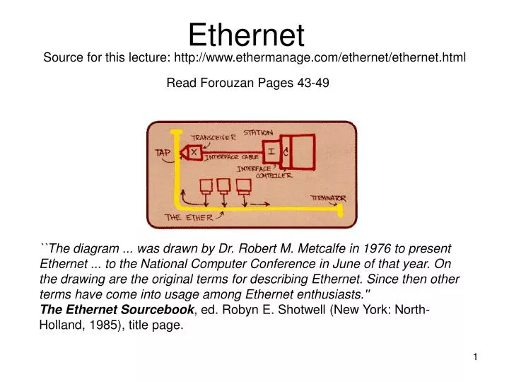
Source for this lecture: http://www.ethermanage.com/ethernet/ethernet.html Ethernet Read Forouzan Pages 43-49 ``The diagram ... was drawn by Dr. Robert M. Metcalfe in 1976 to present Ethernet ... to the National Computer Conference in June of that year. On the drawing are the original terms for describing Ethernet. Since then other terms have come into usage among Ethernet enthusiasts.''The Ethernet Sourcebook, ed. Robyn E. Shotwell (New York: North-Holland, 1985), title page.
Invention of Ethernet “In late 1972, Metcalfe and his Xerox PARC colleagues developed the first experimental Ethernet system to interconnect the Xerox Alto, a personal workstation with a graphical user interface. The experimental Ethernet was used to link Altos to one another, and to servers and laser printers. The signal clock for the experimental Ethernet interface was derived from the Alto's system clock, which resulted in a data transmission rate on the experimental Ethernet of 2.94 Mbps. Metcalfe's first experimental network was called the Alto Aloha Network. In 1973 Metcalfe changed the name to "Ethernet," to make it clear that the system could support any computer--not just Altos--and to point out that his new network mechanisms had evolved well beyond the Aloha system. He chose to base the name on the word "ether" as a way of describing an essential feature of the system: the physical medium (i.e., a cable) carries bits to all stations, much the same way that the old "luminiferous ether" was once thought to propagate electromagnetic waves through space. Thus, Ethernet was born.”
Ethernet Standards • Formal specifications for Ethernet were published in 1980 by a multi-vendor consortium that created the DEC-Intel-Xerox (DIX) standard. This effort turned the experimental Ethernet into an open, production-quality Ethernet system that operates at 10-Mbps. Ethernet technology was then adopted for standardization by the LAN standards committee of the Institute of Electrical and Electronics Engineers (IEEE 802). • The IEEE standard was first published in 1985, with the formal title of "IEEE 802.3 Carrier Sense Multiple Access with Collision Detection (CSMA/CD) Access Method and Physical Layer Specifications." The IEEE standard has since been adopted by the International Organization for Standardization (ISO), which makes it a worldwide networking standard. • The IEEE standard provides an "Ethernet like" system based on the original DIX Ethernet technology. All Ethernet equipment since 1985 is built according to the IEEE 802.3 standard, which is pronounced "eight oh two dot three." To be absolutely accurate, then, we should refer to Ethernet equipment as "IEEE 802.3 CSMA/CD" technology. However, most of the world still knows it by the original name of Ethernet, and that's what we'll call it as well.
Ethernet System Elements The Ethernet system consists of three basic elements: 1. the physical medium used to carry Ethernet signals between computers, 2. a set of medium access control rules embedded in each Ethernet interface that allow multiple computers to fairly arbitrate access to the shared Ethernet channel, and 3. an Ethernet frame that consists of a standardized set of bits used to carry data over the system.
CSMA/CD Protocol • Access to the shared channel is determined by the medium access control (MAC) mechanism which is based on a system called Carrier Sense Multiple Access with Collision Detection (CSMA/CD). • Each interface must wait until there is no signal on the channel, then it can begin transmitting. If some other interface is transmitting there will be a signal on the channel, which is called carrier. All other interfaces must wait until carrier ceases before trying to transmit, and this process is called Carrier Sense. • No one gets a higher priority than anyone else, and democracy reigns. This is what is meant by Multiple Access • Since signals take a finite time to travel from one end of an Ethernet system to the other, the first bits of a transmitted frame do not reach all parts of the network simultaneously. Therefore, it's possible for two interfaces to sense that the network is idle and to start transmitting their frames simultaneously. When this happens, the Ethernet system has a way to sense the "collision" of signals and to stop the transmission and resend the frames. This is called Collision Detect.
Carrier Sense Multiple Access with Collision Detection (CSMA/CD) • Monitor to ensure wire free before transmitted • Monitor during transmission to make sure not garbled by a collision • Once collision detected stop transmission
Collision • If more than one station happens to transmit on the Ethernet channel at the same moment, then the signals are said to collide. The stations are notified of this event, and instantly reschedule their transmission using a specially designed backoff algorithm. As part of this algorithm the stations involved each choose a random time interval to schedule the retransmission of the frame, which keeps the stations from making transmission attempts in lock step. • Repeated collisions for a given packet transmission attempt indicate a busy network. The expanding backoff process, formally known as "truncated binary exponential backoff," is a clever feature of the Ethernet MAC that provides an automatic method for stations to adjust to traffic conditions on the network. Only after 16 consecutive collisions for a given transmission attempt will the interface finally discard the Ethernet packet.
Binary exponential backoff retransmission algorithm • Station encounters first collision randomly select number from set {0,1} • Other station(s) involved in collision select a random value from a set corresponding to number of collisions this other station has experienced. • These randomly chosen values represent how many “slot times” a station must wait before attempting a retransmission. • An Ethernet slot time is 512 bits (64 bytes). For 10 mbit/s Ethernet one bit takes 0.1 microseconds to transmit => slot time is 51.2 microseconds. Note: Minimum size Ethernet frame is 64 bytes. This includes source and destination MAC, type, and CRC fields
The First 10 Rounds of Binary Exponential Backoff Algorithm Round Size Elements of set 1 2 {0,1} 2 4 {0,1,2,3} 3 8 {0,1,2,3….,7} 4 16 {0,1,2,3………..15} 5 32 {0,………………………..31} 6 64 {0,……………………………….{63} 7 128 {0,……………………………………..{127} 8 256 {0,…………………………………………….{255} 9 512 {0,……………………………………………………511} 10 1024 {0,…………………………………………………………{1023} For round 11 through 16 {0,…………………………………………………….{1023} 17 => Excess collision error
Every time a station successfully transmits a frame, it gets to reset its backoff choice set to {0,1}. half duplex -- only one end station may transmit at the same time. full duplex – both end stations may transmit at the same time if desired.
Ethernet Frame Format Original Metcalfe protocol adopted by Digital Equipment, Intel, Xerox. => “DIX” Ethernet. Ethernet 2 is updated same DIX frame format. IEEE Standard 802.3 Not same format If Fail Discard 46 to 1,500 Ethernet: <8> <6> <6> <2> bytes <4> <12> <bytes> Preamble DA SA T DATA CRC Interframe GAP 802.3 <8> <6> <6> <2> <4> <12> Preamble DA SA L DATA CRC Interframe GAP } **Some more stuff here!
Minimum Length • Require a minimum length for CSMA/CD to work correctly • If complete frame is sent before a collision is detected by sender, too late for sender to repeat because MAC layer has discarded the completed frame. • Smallest frame length allowed by standard is a frame of length 51.2 microseconds which is 51.2 microseconds x 10 mbits/seconds = 512 bits (64 bytes) • For 18 bytes of header and the 4 CRC bytes of trailer, 64-18=46 data bytes minimum
Slot Time • Slot time in Ethernet is defined as the round trip time plus the time to send the jam sequence • Slot time is defined in bits and is defined as 512 bits • Slot time in 10 mbit/sec ethernet is 51.2 microseconds
Jam sequence • Assuming a minimum size ethernet frame of 512 bytes • If a sender at one end sends a frame and another sender at the far end also sends a frame, need for the senders to be able to see the collision and to send a jam sequence to inform other stations of the collision. • The round trip time plus the time to send out the jam sequence should be less than the time for a sender to send the minimum frame. Sender must be able to know about the collision before it sends the entire frame.
Maximum Network Length • Maximum length = propagation speed x (slot time / 2) • In wire, electricity travels at 2/3 the rate for travel in air => 2 x 10⁸ m/s • Maximum length for 10 mbit/sec ethernet is (2x10⁸) x ((51.2 x 10⁻⁶)/2) = 5120 meters • Taking into account the delay needed for repeaters, jammers, etc the standard uses only 2,500 meters as the maximum cable length allowed.
Maximum length • The standard defines the maximum allowed frame length to be 1518 bytes. Removing the 18 bytes of header and trailer, data may be no longer than 1,500 bytes. • Maximum limit was due to 1) memory expense so wanted a small buffer and to 2) prevent one computer from dominating the medium
MAC Addresses • The first two fields in the frame carry 48-bit addresses, called the destination and source addresses. The IEEE controls the assignment of these addresses by administering a portion of the address field. The IEEE does this by providing 24-bit identifiers called "Organizationally Unique Identifiers" (OUIs), since a unique 24-bit identifier is assigned to each organization that wishes to build Ethernet interfaces. The organization, in turn, creates 48-bit addresses using the assigned OUI as the first 24 bits of the address. This 48-bit address is also known as the physical address, hardware address, or MAC address. • A unique 48-bit address is commonly pre-assigned to each Ethernet interface when it is manufactured, which vastly simplifies the setup and operation of the network.
Multicast and Broadcast • A multicast address allows a single Ethernet frame to be received by a group of stations. Network software can set a station's Ethernet interface to listen for specific multicast addresses. This makes it possible for a set of stations to be assigned to a multicast group which has been given a specific multicast address. A single packet sent to the multicast address assigned to that group will then be received by all stations in that group. • There is also the special case of the multicast address known as the broadcast address, which is the 48-bit address of all ones. All Ethernet interfaces that see a frame with this destination address will read the frame in and deliver it to the networking software on the computer.
Preamble: AA AA AA AA AA AA AA AB • (64 bits) • Interfame GAP 96 bits 10 Mbits => 9.6 s GAP helps improve fairness of collision detection algorithm. • Ethernet T => Type Field Identifies Protocol • IE 0x0800 => IP • How can we tell which type (DIX or 802.3) frame we received? Look at 2 bytes after MAC fields in the received Ethernet frame: • If this 2 byte field 1500 this is a valid length and we have an 802.3 frame. Since this is 802.3 we have a “Logical Link Control (LLC) subnetwork attachment point (SNAP) Header” which may be used for other purposes with other protocols (like SNA). • If this 2 byte field 1501 This is DIX frame format. No type fields in DIX are ever less than 1501. Thus if you see 1501, it is a DIX frame. Example 0x0800 is a value 1501.
802.3 Special Case => Repackage Old DIX Type Field <1> <1> <1> <3> <2> AA AA 03 000000 DIX Type IE 0x0800 **This is the some other stuff from 2 slides previous.
Purpose of Ethernet • A given Ethernet system can carry several different kinds of high-level protocol data. For example, a single Ethernet can carry data between computers in the form of TCP/IP protocols as well as Novell or AppleTalk protocols. The Ethernet is simply a trucking system that carries packages of data between computers; it doesn't care what is inside the packages.
What is the maximum number of Ethernet frames per second on a 100,000,000 bit per second (One Hundred Megabit per Second) Ethernet network when each Ethernet frame carries 46 bytes of IP data? The size of the Ethernet frame is 6 bytes of Destination MAC Address + 6 Bytes of Source MAC Address + 2 Bytes of Type + 46 Bytes of IP data + 4 Bytes of CRC = 64 Byte Ethernet Frames Each Ethernet frame must have 8 Bytes of Preamble and 12 Bytes of Interframe Gap resulting in 8 + 12 + 64 = 84 bytes transmitted on the wire for each Ethernet frame transmitted. 100,000,000 Bits/sec x (1 Byte/8 Bits) x (1 Frame/84 Bytes) = 148,809.5 From Spirent SmartBits 2000 Port-Pair Throughput ===================== Frame size 64 100 200 300 1000 Ethernet Frame Size in Bytes (Includes overhead byts but not Preamble or Interframe Gap 100Mb MaxRate 148810 104167 56818 39063 12255 Theoretical Maximum Possible Number Frames per second Avg % passed 17.53 25.35 43.80 65.02 99.68 Percent of the Max number possible that actually passed ------------------------------------------------------ 5 to 6 26089 26406 24888 25400 12216 Number of frames that passed our Linux Router
Trivia: Ethernet transmits the most significant byte first but in each byte it transmits the least significant bit first. Important: Ethernet Cables Computer 1 HUB Computer 2 Straight-through Patch Cables Computer 1 Computer 1 Need to use a cross over cable.
Because one pair of wires used to transmit, another pair used to receive transmissions. Must swap transmit/receive. Trivia: In 1979 Metcalfe founded 3 COM Corporation: computers communicate compatibility Neighbor Address Discovery For IP over Ethernet, need a way to discover MAC-Layer addresses of its IP neighbors.
We use an address resolution protocol (ARP) cache. IP uses this helper protocol ARP that runs directly over Ethernet and does not include an IP header. ARP is in RFC-826 ARP sends a frame to the broadcast address (of all 48 bits one). Included in this is the target’s protocol address (IP address). This is the (IP) address of the end station for which we want the MAC address. ONLY the target machine sends its MAC address back to requester. One requester receives ARP reply it stores it for some hold time. Common time is from 15 minutes to 24 hours. (No standard time in RFC-826)
MAC DA = Broadcast MAC SA = Ethermet Frame Header my hardware address ARP Etype ( 0806 ) Enet HW Type (1) Prot Type ( 0800 ) hLen = 6 pLen = 4 OpCode = 1 (Req) Source’s Hardware Address Source’s Protocol Address ARP Packet Payload Target’s Hardware Address Target’s Pro- -tocol Address Padding Padding Padding Padding Frame Check Sequence (CRC - 32) FIGURE 8. 3 Ethernet frame carrying ARP packet.
Example ARP table on a Windows PC: C:\>arp -a Interface: 130.207.231.158 on Interface 2 Internet Address Physical Address Type 130.207.231.1 00-04-de-1b-cf-fc dynamic 130.207.231.12 00-a0-c9-72-52-23 dynamic 130.207.231.161 00-90-27-73-c5-74 dynamic 130.207.231.177 00-a0-c9-31-87-04 dynamic C:\>
LAN interconnection devices operate on “ OSI ” (Open Systems Interconnection Reference Model) Layers: Layer 1 : Physical Layer Layer 2: Data Link Layer Layer 3: Network Layer Application Presentation Application Session Transport Transport Internet Network Subnetwork Data Link Physical Open Systems Interconnection Reference Model Internet Protocol Stack
OSI Layer 1: Repeaters ( Not too common now) HUBS ( Very common ) HUB To Backbone Four HUB rule - only 4 hub hops allowed in a “ Collision Domain ” Hubs are physical layer devices that just “Repeat” what they see, “errored” frames and all. Endstation 1 -- TD+ 2 -- TD- 3 -- RD+ 4 5 6 -- RD- 7 8 Hub Side 1 -- TD+ 2 -- TD- 3 -- RD+ 4 5 6 -- RD- 7 8 Endstation 1 -- TD+ 2 -- TD- 3 -- RD+ 4 5 6 -- RD- 7 8 Endstation 1 TD+ 2 TD- 3 RD+ 4 5 6 RD- 7 8 10 Base-T pinout and Crossover cable HUB attachment Functionality
OSI Layer 2: Bridges ( Not common now ) Switches ( What we call bridges now ) Layer - 2 switches ( Way cool marketing term) Forwarding decisions based only on data link layer header, that is the MAC Destination Address. Use a table made from observing which addresses are seen on each port. No more than 7 bridges in diameter. Today’s ethernet environments use lots of ethernet switches, reducing the collision domain. Collision domain is the set of ethernet segments that can directly hear each others frames. Worst case is all inputs want to go out on the same output. Must have some buffering and some sort of fairness algorithm inside
10 megabit/second • The original standardized Ethernet system operates at 10-Mbps, and there are four base band media segments defined in the 10-Mbps Ethernet standard. • The four media types are shown with their IEEE shorthand identifiers. The IEEE identifiers include three pieces of information. The first item, "10", stands for the media speed of 10-Mbps. The word "BASE" stands for "baseband," which is a type of signaling. Baseband signaling simply means that Ethernet signals are the only signals carried over the media system. • The third part of the identifier provides a rough indication of segment type or length. For thick coax the "5" indicates the 500 meter maximum length allowed for individual segments of thick coaxial cable. For thin coax the "2" is rounded up from the 185 meter maximum length for individual thin coaxial segments. The "T' and "F" stand for "twisted-pair" and "fiber optic," and simply indicate the cable type. • The thick coaxial media segment was the first one defined in the earliest Ethernet specifications. Next came the thin coaxial segment, followed by the twisted-pair and fiber optic media segments. The twisted-pair segment type is the most widely used today for making network connections to the desktop.
100 megabit/second • Compared to the 10-Mbps specifications, the 100-Mbps system results in a factor of ten reduction in the bit-time, which is the amount of time it takes to transmit a bit on the Ethernet channel. This produces a tenfold increase in the speed of the packets over the media system. However, the other important aspects of the Ethernet system including the frame format, the amount of data a frame may carry, and the media access control mechanism, are all unchanged. • The Fast Ethernet specifications include mechanisms for Auto-Negotiation of the media speed. This makes it possible for vendors to provide dual-speed Ethernet interfaces that can be installed and run at either 10-Mbps or 100-Mbps automatically.
100 megabit/second • The first item, "100", stands for the media speed of 100-Mbps. The "BASE" stands for "baseband," which is a type of signaling. Baseband signaling simply means that Ethernet signals are the only signals carried over the media system. • The third part of the identifier provides an indication of the segment type. The "T4" segment type is a twisted-pair segment that uses four pairs of telephone-grade twisted-pair wire. The "TX" segment type is a twisted-pair segment that uses two pairs of wires (This is what we are using in the lab). The "FX" segment type is a fiber optic link segment based on the fiber optic physical medium standard that uses two strands of fiber cable. The TX and FX medium standards are collectively known as 100BASE-X.