Download
1 / 55
550 likes | 651 Views
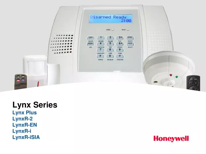
Lynx Series Lynx Plus LynxR-2 LynxR-EN LynxR-i LynxR-iSIA. Agenda. Panel Features Connecting an AlarmNet Communicator Programming Locations *56 Enhanced Zone Programming *80 Device Programming *81 Zone List Programming. Features. AlarmNet Communicator Compatible *

E N D
Agenda • Panel Features • Connecting an AlarmNet Communicator • Programming Locations • *56 Enhanced Zone Programming • *80 Device Programming • *81 Zone List Programming
Features • AlarmNet Communicator Compatible * • IP/GSM Downloading Compatible * • Wireless Siren Compatible – 5800WAVE • Wireless Keypad Compatible – 5828V Fixed English • Built in Speakerphone • Built in Remote Phone Control • Built-in Two-way voice system - AAV • Numeric Pager Reporting • Follow-Me Alarm Reporting (voice message) • * Options of the Lynx Plus, LynxR-2 and LynxR-i • Central Station reporting required for Pager and Follow-Me Alarm reports except for Open and Close reports
Plus Features • Supports two-way voice over GSM radio • with the GSMVLP radio module • Full 16-button keypad with easy-to-read LCD display and status LEDs • 2” x 16” Custom Alpha backlit display • Hinged cover for simpler installations
Features • Rechargeable batteries • 6 x 1.2V Nickel Metal-Hydride pack • provides 24 hours of standby • Enhanced Enroll Mode • Can enroll Confirm serial number • View serial number • Change loop number w/o deleting • RF jam detection
Features • 1 Hardwire zone – Not present on LynxR-2 or LynxR-i • 24 Wireless zones • 16 Button zones • 5804, 5804BD, BDV, & 5802MN • 8 user codes • 1 installer • 1 master • 1 duress • 5 standard • 84 Event log – Viewable from Compass Only • On-board UL 85db siren
AlarmNet Communicator GSMVLP Status LEDs Signal Strength LED Must be solid. Registration and Test Switch
Lynx Plus AlarmNet Communicator Mounting Installing the GSMVLP Module
AlarmNet Communicator Connection Wiring Connections and Routing
AlarmNet Communicator GSML Status LEDs Signal Strength LED Must be solid. Registration and Test Switch
AlarmNet Communicator Connections LynxR-2/R-i & 7847i-L Configuration B
AlarmNet Communicator Connections LynxR-2/R-i & 7845GSM / 7845i-GSM Do Not Connect the 7845GSM internal battery! NOTE: DC Power is supplied from Lynx panel.
AlarmNet Communicator Connections LynxR-2/R-i & 7847i
AlarmNet Communicator Connections LynxR-EN & AlarmNet Device 2K Ohm Pull up resistor. Program your AlarmNet Device in V- (neg) Zone Mode.
AlarmNet Communicator Connections LynxDM-GSM
Programming Locations * 20 Installer Code [4112] Example 1 To change the Inst. Code you would enter *20 then the new code: For example: Change Installer code to 4321 * 2 0 4 3 2 1 (after entry of last digit the keypad will beep 3 times to confirm the entry and automatically proceed to location *21)
Programming Locations *20 Installer Code [4112] Example 1 To view what is in location *20 you would enter: # 2 0 the panel will then display the location contents one digit at a time (in hexadecimal format) For example: # 2 0then the panel would display: 04 (beep) 03 (beep) 02 (beep) 01 (beep, beep, beep) The installer code is 4321. A triple beep is heard after the last digit of the field is displayed.
Programming Locations [1] 0 = no; 1=yes *21 Quick Arm Enable [0] 0 = always on 1 = off after 10secs *22 Keypad Backlight Time Out *24 RF House ID Code [00] 00 = disable 01-31 = house ID
Programming Locations *25 Powerline Carrier device House Code [0] *26 Chime by Zone [0] 0 = no; 1 = yes Program zones to chime on zone list 3 [0] 0 = no limit *31 Single Alarm Sounding/Zone 1 = yes, once per arming [0] *31 Single Alarm Sounding/Zone SIA 0 = Same as Shutdown in field *92 1 = yes, once per arming period [1] 0 = none; 1 = 4min *33 Alarm Bell Timeout 2 = 8min; 3 = 12min; 4 = 16min
Programming Locations Daylight Saving Time [3,11] *29 Daylight Saving Time Start/End Month This is March and November. *30 Daylight Saving Time Start/End Weekend [2,1] This is the 2nd Sunday in March and the 1st Sunday in November.
SIA Entry Exit Times *34 Exit Delay [6,0] 00-99 = exit delay time (in sec) 97 = 120 sec delay SIA: Must be set to a minimum 45 sec. *35 Entry Delay 1 (zone type 01) [3,0] 30-96 = entry delay time (in sec.) 97 = 120 sec; 98 = 180 sec; 99 = 240 sec SIA: Theentry delay must be set to a minimum of 30 seconds. The sum of entry delay 1 field *35 and the burglary abort window entered in *50 should not exceed 1 minute.
SIA Entry Exit Times [3,0] *36 Entry Delay 2 (zone type 02) 30-96 = entry delay time (in sec.) 97 = 120 sec; 98 = 180 sec; 99 = 240 sec SIA: Theentry delay must be set to a minimum of 30 seconds. The sum of entry delay 2 field *36 and the burglary abort window entered in *50 should not exceed 1 minute. [0] 0 = no; 1 = yes *50 15 sec Dialer Delay (Burg) [2] 1 = 15 sec; 2 = 30 sec; 3 = 45 sec *50 Burglary Abort Window SIA
Phone Options [0] *38 Confirmation of Arming Ding 0 = no; 1 = yes (when armed by self-contained keypad or RF) 2 = yes (when armed by RF only) *40 PABX Access Code SIA PABX/Call Waiting Disable *41 Primary Phone No. Up to 6 digits ... Up to 20 digits
Phone Options *42 Secondary Phone No. … Numeric Pager or Follow-Me Alarm Up to 24 digits *43 Primary Account Number *44 Second Account Number 4 or 10 Digits [ FFFF ] 4 or 10 Digits [ FFFF ] The Account Number will be 10 digits only if 10 Digit Contact ID Format is selected in *48 Report Format.
Phone Options *46 Follow-Me Reminder Phone Number … Up to 24 digits [5] *47 Phone System Select
Phone System Select SIA Only SIA Only [5] *47 Phone System Select
Format *48 Report Format for PRIM/SEC. [ 7,7 ] Primary Secondary 0 = 3+1, 4+1 Ademco L/S Standard 6 or undefined = 4+2 Ademco Express 1 = 3+1 4+1 Radionics Standard 7 = Ademco Contact ID reporting 2 = 4+2 Ademco L/S Standard 8 = 3+1, 4+1 Ademco L/S Expanded 3 = 4+2 Radionics Standard 9 = 3+1, 4+1 Radionics Expanded 5 = Ademco 10 Digit Contact ID Format NOTE: Option 5 or 7 (Ademco Contact ID) must be selected for AAV. • ADEMCO Contact ID Example: • 1234 E 131 00 C005 • This is a new Perimeter Alarm on Zone 5, • Account #, the Event (E = new, R = restore ) • Event Code, Zone #
Reporting Options Dialer Programming [0]0 = Disable (Backup report only) *49 Split/Dual Reporting TO PRIMARY PHONE No. TO SECONDARY PHONE No. 1 = Alarms, Restore, Cancel Others 2 = All except Open/Close , Test Open/Close, Test 3 = Alarms, Restore, Cancel All 4 = All except Open/Close, Test All 5 = All All TO PRIMARY PHONE No. TO PAGING No. (Secondary) 6 = All except Open/Close Alarms, Open/Close‡, Troubles 7 = All reports Alarms, Trouble 8 = All reports Alarms, Open/Close‡, Troubles 9 = All except Open/Close Open/Close‡ TO PRIMARY PHONE No. TO Follow-Me Alarm No. (Secondary) 10 = All except Open/Close Alarms, Open/Close‡, Troubles 11 = All reports Alarms, Trouble 12 = All reports Alarms, Open/Close‡, Troubles 13 = All except Open/Close Open/Close‡ ‡ Will report users 0, 5-8 or wireless arm/disarm button Zones 26-33; all other zones and users do not report
Periodic Test *51 Periodic Test Report [0] 0 = none; 1 = 24 hrs; 2 = weekly; 3 = 30 days [2] 0 = 24 hr; 1 = 6 hrs; *52 First Test Report Offset 2 = 12 hrs; 3 = 18 hrs [1,0] *64 Test Report Code [0,0] *76 Test Restore Report Code SIA Sent when test mode is exited.
Programming Locations *59 Exit Error Report Code [1] *60 Trouble Report Code [1,0] [0] *65 Open Report Code [0,0] *66 Arm Away/Stay Rpt Code STAY AWAY
Programming Locations *55 Enable LRR/IP Communications Device [0] 0 = Disable; 1 = Enable *77 Dynamic Signaling Delay/ Dynamic Signaling Priority [0, 0] 1st Entry (delay before switching Central Station reporting path) 2nd Entry 0 = Primary Dialer First 1 = LRR/IP First 2 = LRR/IP Reporting Only 0 = Redundant reporting 1 = 15 seconds 2 = 30 seconds 3 = 45 seconds 4 = 60 seconds 5 = 75 seconds 6 = 90 seconds 7 = 105 seconds 8 = 120 seconds 9 = 135 seconds #10 = 150 seconds #11 = 165 seconds #12 = 180 seconds #13 = 195 seconds #14 = 210 seconds #15 = 225 seconds
Programming Locations *87 Aux Function 1-button paging or Macro • Send 999-9999 to a pager or can be a Macro *88 Pager Characters • Enter up to 16 digits as needed for customizing pager messages or pager requirements (PIN’s etc.) *90 Event Logging [3] 0 = None; 1 = Alarm/Alarm Restore 2 = Trouble/Trouble Restore; 4 = Bypass/Bypass Restore; 8 = Open/Close To select all, enter #15
Programming Locations *91 Alarm Audio Verification/Remote Phone Control [2] 0 = None; 1 = AVM & remote phone control 2 = remote phone control only 4 = AVM only *92 Number Of Reports in Armed Period [0] 0 = 10 Alarm/Alarm Restore Reports; 1 = Unlimited [1] *92 Swinger Shutdown SIA 1 = shutdown after one alarm 2 = shutdown after two alarms
Programming Locations *94 Download Phone No. … Up to 20 Digits *95 Ring Detect Count for Downloading [0] 0 = Disable Station Initiated Download; 1-14 = Number of rings; 15 = Answering Machine Defeat
Programming Locations *96 Initializes Download ID, Subscriber Account No. For Initial Download; No entry required *97 Select 1 of 4 Default Option Setups. Enter 1-4 to select from default tables 1-4. Enter 0 to abort. *98 Exits Programming mode and prevents re-entry by Installer Code +8+0+0 *99 Exits Programming mode and allows re-entry by Installer Code +8+0+0
*56 Enhanced Zone Programming Zone Number Enter the 2-digit zone number to be programmed [*] = Continue 00 = exit zone programming mode A 02 A 02 ZONE NUMBER Zone Type b 01 Enter the 2-digit zone type. [*] = Continue b 01 ENTR/EXIT#1 ZONE TYPE
*56 Enhanced Zone Programming C 10 Report Code C10 REPORT CODE Enter the report code Input Type d 3 Enter the input type 3 = Supervised RF (RF) 4 = Unsupervised RF (UR) 5 = Button type (BR) [*] = Continue d 3 RF SUPERVSD INPUT TYPE E 1 Loop Number E2 LOOP#/AUTO LEARN • It takes 4 transmissions to learn in the Serial and Loop Numbers. • 1st Fault and Restore – a single beep will sound. • 2nd Fault and Restore – a double beep will sound. • If a voice descriptor is already programmed for the zone, it will also be announced.
*56 Enhanced Zone Programming E 2L An “L” will appear after the loop number if the loop number was learned in. E2L LEARNED LOOP#/AUTO LEARN 1A L 1AL A000-1234 ENROLL MODE Enroll Mode 0 = Skip to the VOICE DESCRIPTOR prompt (1C) 1 = Enroll now and proceed to SERIAL NUMBER prompt (1b) (If “ L” is not displayed) 2 = Copy the last serial number from the local memory buffer (If “L” is not displayed) 3 = View existing serial number. (Only if “L” is displayed) 9 = Delete existing serial number. (Only if “L” is displayed) [*] = Advance to the VOICE DESCRIPTOR prompt (1C)
*56 Enhanced Zone Programming Manual Serial Number Entry 1A Press [1] at the 1A prompt to manually enter the transmitters serial number 1A ENROLL MODE 1b Manually enter the transmitter’s 7-digit serial number. When all 7 digits are entered, press the [*] key. 1b SERIAL NUMBER 1A L After entry is completed, you may trip the transmitter to confirm the serial number entry is correct, or press [*] to skip. 1AL A000-1234 ENROLL MODE
*56 Enhanced Zone Programming 1C • Voice Descriptor • (Can also be entered separately in *84) 1C ZONE DESCRIPTOR 0 = skip to next zone 1 = Enter descriptor mode 1d 47 Descriptor 1 1d47 Front Enter [#] + 2 digit vocabulary index number 6 = accept word and advance to descriptor 2 8 = accept word and advance to next zone FRONT
*56 Enhanced Zone Programming 1E 69 Descriptor 2 1E69 Sliding Enter [#] + 2 digit vocabulary index number 6 = accept word and advance to descriptor 3 8 = accept word and advance to next zone SLIDING 1F 12 Descriptor 3 1F04 Door Enter [#] + 2 digit vocabulary index number 8 = accept word and advance to next zone (A prompt) DOOR A 03 A03 ZONE NUMBER 00 = exit zone programming mode
*80 Device Programming Device Programming 80 0 = Exit mode 1 = Enter mode 80 DEVICE PROG MENU Device Number A01 Enter the 2-digit device number 01-08 = X-10 09-16 = Multi-Mode Total Connect [*] = Continue 00 = Exit Device Programming mode A01 DEVICE NUMBER Device Action b 2 Enter the 1-digit action 0 = No response 1 = Close for 2 seconds 2 = Close and stay closed 3 = Pulse on and off [*] = Continue b02 DEVICE ACTION
*80 Device Programming Start Event Type C 2 C02 START EVENT TYPE Enter the 1 – digit start event type 0 = Not used 3 = Trouble 1 = Alarm [*] = Continue 2 = Fault d 1 Start Zone List d01 START ZONE LIST Enter the 1– digit zone list number, 1-3, or 0 if not used; [*] = Continue
*80 Device Programming Start Zone Type E 00 Enter the 2-digit start zone type [*] = Continue E00 START ZONE TYPE F 0 Stop Zone List F00 STOP ZONE LIST Enter the 1-digit zone list number, 1-3, or 0 if not used [*] = Continue 1A22 Stop Zone Type 1A22 STOP ZONE TYPE Enter the 2-digit stop zone type [*] = Return to Device Number prompt (A) A02 DEVICE NUMBER A02