Download
1 / 40
400 likes | 517 Views
JLab Polarized Source. Happex Collaboration Meeting May 18, 2007 P. Adderley, J. Brittian, J. Clark, J. Grames, J. Hansknecht, M. Poelker, M. Stutzman, R. Suleiman, K. Surles-Law. Outline. G0 Experience: Laser-Table Setup, Halls Cross-talk, … Helicity Magnets Commissioning

E N D
JLab Polarized Source Happex Collaboration Meeting May 18, 2007 P. Adderley, J. Brittian, J. Clark, J. Grames, J. Hansknecht, M. Poelker, M. Stutzman, R. Suleiman, K. Surles-Law
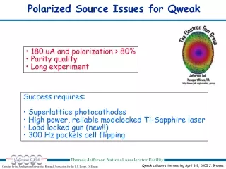
Outline G0 Experience: Laser-Table Setup, Halls Cross-talk, … Helicity Magnets Commissioning Q-weak 250 Hz Helicity Flip Test and the New HV Switch FFB Diagnostic and Measuring Parity-Quality of Beam Paper: “Conducting Parity Violation Experiments at CEBAF” Mott Polarimetry, Load-Lock Gun, and more …
Summary of G0 Experience Pockels Cell (PC) HVs, roll, pitch, and yaw should be optimized using the spinning HWP and a scope. No need to do laser work with the QPD in the tunnel. PC x & y should be optimized to minimize the steering with the electron beam; since Jan 07, automated PC X & Y stages were installed. Use PITA and RHWP to zero the charge asymmetry and position differences (with the electron beam).
On the Laser Table IN / PITA=0 Choose: x=0, y=90 mils
On the Laser Table OUT / PITA=0 Choose: x=70, y=90 mils
With the electron beam OUT / PITA=0 Choose: x=67, y=91 mils
Laser Table Setup and Pockels Cell Alignment (G0 Experience): • Laser Table: • Check laser spot is round (1mm diameter) and has no tails or satellites and centered on the Pockels Cell. • With the spinning HWP in front of LP, minimize the residual linear polarization. Find the optimal +HV, -HV, roll, pitch, and yaw of the PC. Check for both IHWP= IN & OUT. • Electron Beam: • Establish electron beam in the injector. Find the BPMs pedestals by doing a current scan with the iocse’s set in “Gains off” mode. • Turn OFF the PC and take a long run to check for electronic noise. Turn it back ON. • You will use IPM1I02 to finish the setup but it’s good to check IPM1I04 and IPM1I06. • Do an x & y translational scans for both IN and OUT. Find PC x & y that minimize the PC steering. • For IN, do a RHWP at PITA=0 and another one at PITA=-180 V. Find the RHWP angle that further minimizes the position differences and charge asymmetry, you will have to change the PC high voltage to new values. Repeat this for OUT. • Now for both IN and OUT you have determined: PC x, PC y, +HV, -HV, RHWP angle. The IA voltage should be 5 V for both IN and OUT. Over time, IN and OUT will drift to their own IA values.
Halls A & C Cross-talk • Hall A IA Scan: • Hall A IA Scan (80 uA) • Hall C Charge asymmetry and position differences during the Hall A IA Scan (20 uA)
Hall C Charge Asymmetry Width: Hall C @ 20 uA Hall A @ 90 uA Hall C @ 20 uA Hall A OFF
Injector Helicity Magnet Installation (0L01-0L03) January 5-6, 2004 MHE0L03V, MHE0L03H MHE0L02H MHE0L01V 110 VAC Isolation Transformer Grounded cage containing electrically isolated helicity magnet controls (VME) Tube protecting Litz magnet wire
Calibration • Each magnet can kick both helicity states • Very small coupling to charge asymmetry (100 times smaller than PZT) • The position feedback is not coupled to the charge feedback • Can do position feedback on both position and angle in x & y
Position Feedback Test I • Introduce large position differences: Magnet 1 at even DAC = 500
Turn ON position feedback: Zero position differences at 0L05 and 0L06
Position Feedback Test II • Introduce large position differences: Move the Pockels Cell from its optimal position on the laser table
Turn ON position feedback: Zero position differences at 0L05 and 0L06
Position Feedback Test III: • 1-day G0 Production:
Electrical Pick-up • One big concern: Will other elements on the beam-line see the helicity signal? Check this with Pockels Cell OFF and Helicity Magnets OFF.
Turn ON magnet 1: Power it to 1000 times its operational value. Look for position differences upstream the magnet
Summary: Helicity Magnets can be used to do position feedback Some improvements are still needed … • Increase the DAC resolution by at least a factor of 10. • Better selection of BPMs to do feedback on.
Commissioning of the 250 Hz Helicity Flip and the New HV Switch
Changes needed to run at 250 Hz • New Pockels Cell HV Switch to replace the old switch • The Helicity Board is programmed for either 30 Hz or 250 Hz with Time-Settle of 60 us, 100 us, 200 us, or 500 us • Check that tools we need still can work at 250 Hz and 60 us T-Settle: • Parity DAQs • Mott and Moller Polarimeters • Helicity Magnets • … Worked Fine
Issue I:New Switch Electrical Pickup 30 Hz Flip PC OFF, new Switch 30 Hz Flip PC OFF, old Switch
Issue II: 60 Hz Position Noise Can 60 Hz noise be used to study the beam envelope?
More 60 Hz noise search to be continued … After moving an ion-pump power supply away from the beam-line
FBB Diagnostic and Measuring Parity-Quality of Beam Richard Dickson
The Accelerator BPM Measurement • Developed by Richard Dickson. • It uses the FFB diagnostic system to read the BPMs wires. Currently running on iocse9 in Hall A and iocse14 in Hall C. These two IOCs receive only the delayed helicity signal. • Each wire is sampled at 1800 Hz: for Hall A (Linac style SEE BPM) each sample is 64 us long and consists of 8 sub-samples each 8 us. For Hall C (Transport style BPM) a single sample is taken at the 1800 Hz rate. Two seconds of data are acquired for each helicity state (~3600 samples). For each five second readout, one second is reserved for computation and output by EPICS. • For each sample: • The 4-wires (pedestal subtracted) are added for all the BPMs in each feedback system (eight), and x & y positions are calculated individually for each BPM • Data Processing: • Data is summed for any given helicity window and the sum stored for later correlation with the delayed helicity signal. There is a dead time at both beginning and end of the helicity window. Beam trips are filtered away. • This results in roughly 60 samples being summed together in any helicity window. • The helicity correlated sum for a window are then further summed into a running total for that state until approx two seconds of data are acquired per state. • After completion of data acquisition, asymmetries and differences are computed. These are then available via EPICS as well as values that are further digitally filtered.
Measuring Position Differences Helicity Magnet 1 ON +/- 150 DACs
Results • Charge asymmetry and position differences agree to better than 10%. • Modify the BPM software to calculate also error bars or RMSs. • Hardware and software changes to the Injector IOCs to be able to measure helicity correlated properties in the Injector (iocse11, iocse12, iocse19 – 23 BPMs) – July – Sept. 07
Paper Idea: Conducting Parity Violation Experiments at CEBAF. Target Journal: Phys Rev A orNuclear Instr and Methods A or Rev of Scientific Instr. First draft due by July 1st, 2007. Format: plain text or doc or latex – I will put things together in Latex. Figures: “eps” format. Collaboration (in no particular order, who did I forget?): JLab: Suleiman (POC), Hansknecht, Poelker, Grames, Chao, Kazimi, Bogacz, Dickson … HAPPEx: Paschke (POC), Cates, Kumar, Souder, Michaels, Kaufman, Snyder … G0: Pitt (POC), Armstrong, Nakahara, Bailey … Topics (in no particular order, what did I forget?) Introduction: (Armstrong☺) Recall first parity violation experiments at accelerators Discuss the family of recent parity violation experiments, what makes them different, what makes them possible? How do we do a parity violation experiment? Laser table: Lasers (diodes, ti-sap, fiber) (Poelker ☺) Pockels cell properties Pockels cell alignment techniques (Happex method) Laser table components: IA, pzt, insertable halfwave plate, Rotatable HWP Pockels cell HV switch (Hansknecht ☺) Comparison of commercial PCs (Cleveland, lasermetrics, 10mm, 20mm, RTP) PZT mirror position feedback (Pitt ☺) Flipping schemes (pairs, quartets), delayed reporting (Pitt ☺) Ground loop management (Hansknecht ☺) Photo-cathodes: types, Residual LP, Analyzing power, QE gradients… Accelerator: Beam position monitors (Dickson☺) Beam charge monitors Using the bpm system to measure asymmetries (Dickson☺) Beam envelop management at injector (beam through holes) (Kazimi ☺) Beam envelop matching throughout machine, adiabatic damping (Chao☺): Characterization and control of global transport optics Correction of XY coupling and transport singularity from 100 keV to 60 MeV Tools and methods for minimizing transport irregularities Phase Trombone to minimize position differences at target (Bogacz ☺) Halls Crosstalk and beam loading Feedback Coil Modulation, Dithering vs. Regression Position feedback using helicity magnets (Grames, Suleiman ☺) Summary: (Armstrong ☺) What has been achieved so far in terms of position differences and charge asymmetries? Future experiments (Qweak and Lead neutron radius) and their requirements, trends and need for continued R&D.
Upgrade the 5 MeV Mott DAQ: Reduce background and improve the statistical error bar • Install new 100 keV / 500 keV Mott in Injector in August 07 • Load-Lock Gun will be installed in July 07 (4 photo-cathodes) • Now running using fiber-lasers • PC HV Switches and Ground Loop Elimination: (Hansknecht) • Switch Designs • Eliminating Ringing in Pockels Cells used in Parity experiments • Ground loop elimination for Parity experiments http://www.jlab.org/accel/inj_group/laser2001/pockels.htm