Download
1 / 16
190 likes | 438 Views
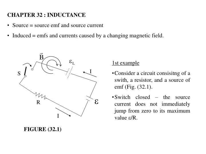
I. S. R. I. CHAPTER 32 : INDUCTANCE Source = source emf and source current Induced = emfs and currents caused by a changing magnetic field. 1st example Consider a circuit consisitng of a swith, a resistor, and a source of emf (Fig. (32.1).

E N D
I S R I • CHAPTER 32 : INDUCTANCE • Source = source emf and source current • Induced = emfs and currents caused by a changing magnetic field. • 1st example • Consider a circuit consisitng of a swith, a resistor, and a source of emf (Fig. (32.1). • Switch closed – the source current does not immediately jump from zero to its maximum value /R. FIGURE (32.1)
Faraday’s Law • As the source current increases with time, the magnetic flux through the circuit loop due to this current also increases with time. • This increasing flux creates an induced emf in the circuit. • The direction of the induced emf is such that it would cause an induced current in the loop. • This would establish a magnetic field that would oppose the change in the source magnetic field. • Thus, the direction of the induced emf is opposite the direction of the source emf; this results in a gradual rather than instantaneous increase in the source current to its final equilibrium value. • This effect is calledself-inductionbecause the changing flux through the circuit and the resultant induced emf arise from the the circuit itself. • The emf L set up in this case is called a self-induced emf or a back emf.
2nd example • Figure (32.2) – a coil wound on a cylindrical iron core. • Assume that the source current in the coil either increases or decreases with time. • Figure (32.2a) - When the source current is in the direction shown, a magnetic field directed from right to left is set up inside the coil. • As the source current changes with time, the magnetic flux through the coil also changes and induces an emf in the coil. • Lenz’s Law – the polarity of this induced emf must be such that it opposes the change in the magnetic field from the source current. • Figure (32.2b) – Show the polarity of the induced emf if the source current is increasing (closed circuit). • Figure (32.2c) – show the polarity of the induced emf if the source current is decreasing (opened circuit).
(32.1) • Quantitative description of self-induction • A self-induced emf L is always proportional to the time rate of change of the source current. • B B and B I, thus B I • For a closely spaced coil of N turns (a toroid or an ideal solenoid) carrying a source current I, we find that : • where L is a proportionality constant – called the inductance of the coil (depends on the geometry of the circuit and other physical characteristics. • The inductance of a coil containing N turns is : Self-induced emf Inductance of an N-turn coil (32.2) Same flux passes through each turn
From Equation (32.1), we can also write the inductance as the ratio : • Inductance is a measure of the opposition to a change in current. • The SI unit of inductance is the henry (H), which is 1 volt-second per ampere (Equation (32.3)). • Example (32.1) : Induxtance of a Solenoid • Find the inductance of a uniformly wound solenoid having N turns and length . Assume that is much longer than the radius of the windings and that the core of the solenoid is air. Inductance (32.3)
Solution • We can assume that the interior magnetic field due to the source current is uniform and given by Equation (30.17) : • where n = N/ is the n umber of turns per unit length. • The magnetic flux throught each turn is : • where A is the cross-sectional area of the solenoid. • Using this expression and Equation (32.2), we find that : • Because N = n , we can express the result in the form : (32.4) V = volume of the solenoid = A
Example (32.2) : Calculating Inductance and emf • Calculate the inductance of an air-core solenoid containing 300 turns if the length of the solenoid is 25.0 cm and its cross-sectional area is 4.00 cm2. • Calculate the self-induced emf in the solenoid if the current through it is decreasing at the rate of 50.0A/s. • Solution for (a) • Using Equation (32.4), we obtain : • Solution for (b) • Using Equation (32.1) and given that dI/dt = -50.0A/s, we obtain :
32.1) RL CIRCUITS • If a circuit contains a coil, such a s a solenoid, the self-inductance of the coil prevents the current in the circuit from incrasing of decreasing instantaneously. • A circuit element that has a large self-inductance is called an inductor and has the circuit symbol . • Because the inductance of the inductor results in a back emf, an inductor in a circuit opposes changes in the current through that circuit. • If the battery voltage in the circuit is increased so that the current rises, the inductor opposes this change, and the rise is not instantaneous. • If the battery voltage is decreased, the presence of the inductor results in a slow drop in the current rather that a immediate drop.
I a R + + L - - b S (32.6) • The back emf is, from Equation (32.1) : • Because the current is increasing, dI/dt is positive; thus L is negative. • This negative value – reflects the decrease in electric potential that occurs in going from a to b across the inductor, as indicated by the +ve and -ve signs (Figure (32.3)). • Apply Kirchhoff’s loop rule (clockwise direction) : FIGURE (32.3) • (Figure (32.3) – an RL circuit because the elements connected to the battery are a resistor and an inductor. • Switch S is thrown closed at t=0 the current in the circuit begins to increase – and a back emf that opposes the increasing current is induced in the inductor.
A mathematical solution of Equation (32.6) represents the current in the circuit as a function of time. • To find this solution, we change variables for convenience, letting : • so that dx = - dI. • With these substitutions, we can write Equation (32.6) as : • Integrating this last expression, we have : • where xo = the value of x at time t=0. • Taking the antilohrarithm :
(32.7) • Because I=0 at t=0, from the definition of x : xo=/R. • Hence, this last expression is equivalent to : • The current does not increase instantly to its final equilibrium value when the switch is closed but instead increases according to an exponential function. • We can also write this expression as : • where the constant is the time constant of the RL circuit : = L / R (32.8) • is the time it takes the current in the circuit to reach (1-e-1) = 0.63 of its final value /R. Effect of the inductor
I t t (32.9) FIGURE (32.4) • Investigation of the time rate of change of the current in the circuit. • Taking the first time derivative of Eq. (32.7), we have : • The time rate of change of the current is a maximum (equal to /L) at t=0 and falls off exponentially to zero as t approaches infinity (Figure (32.5)). • Figure (32.4) – shows a graph of the current versus time in the RL circuit. • The equilibrium value of the current, which occurs as t approaches infinity, is /R (by setting dI/dt=0 in Eq. (32.6) and solving for the current I). • At equilibrium, the change in the curent is zero. • Thus, the current initially increases very rapidly and then approaches the equilibrium value /R as t approaches infinity. FIGURE (32.5)
L R a b S2 S1 - + (32.10) • S2 closed, S1 opened – the circuit is described by upper loop (Fig. (32.6)). • The lower loop no longer influences the behavior of the circuit – a circuit with no battery ( = 0). • Kirchhoff’s loop rule to the upper loop, we obtain : • The solution of the differential equation: • where = the emf of the batery and Io=/R is the current at t=0, the instant at which S2 is closed as S1 is opened. FIGURE (32.6) • Figure (32.6) – rl circuit (contains two switches that operate such that when one is closed, the other is opened. • S1 closed for a length of time sufficient to allow the current to reach its equilibrium value /R. • The circuit is described by the outer loop (Figure (32.6).
I t • When battery were removed from the circuit : • No inductor in the circuit - the current would immediately decrease to zero. • With inductor in the circuit – it acts to oppose the decrease in the current and to maintain the current. • Figure (32.7) – A graph of the current in the circuit versus time shows that the current is continuously decreasing with time. • The slop dI/dt is always negative and has its maximum value at t=0. • The negative slope signifies that L= - L(dI/dt) is now positive; that is, point a in Figure (32.6) is at a lower electric potential thant point b. FIGURE (32.7)
30.0 mH 6.00 12.0 V 2 S (a) t (ms) 0 (b) Example (32.3) : Time Constant of an RL Circuit The switch in Figure (32.9a) is thrown closed at t=0. (a) Find the time constant of the circuit. (b) Calculate the current in the circuit at t = 2.00ms. (c) Compare the potential difference across the resistor with that across the inductor. I(A) FIGURE (32.9)
Solution for (a) • The time constant is given by Equation (32.8) : • Solution for (b) • Using Equation (32.7) for the current as a function of time (with t and in milliseconds), we find that at t=2.00 ms : • A plot of Equation (32.7) for this circuit is given in Figure (32.9b). • Solution for (c) • At the instant the switch is closed, there is no current and thus no potential difference across the resistor. • At this instanst