Download

1 / 44
720 likes | 1.39k Views
Blower Door Testing Basics. IAQ Diagnostic Tools for Tribal Professionals. Testing House Tightness. House Air Leakage Testing. Building Air Leakage/Tightness Testing. Closed house condition Blower door creates negative pressure Measure house pressure + air flow out

E N D
Blower Door Testing Basics IAQ Diagnostic Tools for Tribal Professionals
Testing House Tightness
Building Air Leakage/Tightness Testing Closed house condition Blower door creates negative pressure Measure house pressure + air flow out Use - 50 pascal pressure High air flow @ 50 pascals = large air leakage Low air flow @ 50 pascals = small air leakage
Exceptions to Negative PressureBlower Door Testing • Test house with Pressurization when presence of pollutants or irritants may be pulled into a home: • Vermiculite insulation • Asbestos, fiberglass, Molds, etc. • Cover exhaust fans and other openings with back-draft dampers
Measure the pressure in building Measure the volume of air out fan Calculate the leakage area Estimate air exchange
Fan Door Test 1) Depressurize building to negative - 50 pascals 2) Measure how much air (cfm) required to maintain 50 pascals -50 CFM Larger leakage = Higher CFM
Fan Door Test 1) Depressurize building to negative - 50 pascals 2) Measure how much air (cfm) required to maintain 50 pascals -50 CFM Smaller leakage = Lower CFM
Leakage Test Equipment Door Panel & Frame Fan & Rings Pressure Gauge
DG-700 Pressure & Flow Meter Device Configuration Select Device Select Mode Select “Input” ports “REF” ports
BD = Blower Door OPEN BD 3 Pa CFM 1 PR/ FL
OPEN BD 3 Pa CFM 1 PR/ FL
OPEN BD 3 Pa CFM 1 PR/ FL
OPEN BD 3 Pa CFM 1 PR/ FL
DG-700 Pressure & Flow Meter – Conventional Blower Door Connection Red tube “Input” port to Fan Green tube “REF” port to Outside
OPEN BD 3 BD 3 “ Blower Door “ Pa CFM PR/ FL 1
Interior With Respect to (WRT) Outdoors - 50PA - 50. A B AH A B Basic Blower Door Test Green Tube Outside Channel A “Reference” Red Tube Fan CFM Channel B “Input”
Red Tube Fan CFM Channel B “Input” Green Tube Outside Channel A “Reference”
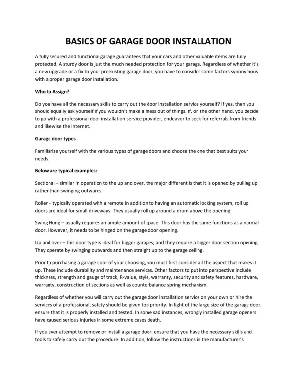
Set-up • Assemble frame and adjust to door size • Remove frame and place nylon panel over frame • Place panel and frame in door opening and tighten • Insert fan in panel • Connect tubing to manometer, fan and exterior • Depressurize to 50Pa and record CFM in older homes, pressurize if necessary
During Testing • Exterior windows and doors closed • Fireplace and stove doors closed • Close dampers (depressurizing the house sucks gravity dampers closed) • Interior doors open
During Testing • Open access hatches to conditioned attics or crawl spaces • Exterior ventilation openings closed and sealed • HVAC ducts and registers not sealed • HVAC, water heater, OFF
What the numbers mean Pressure (in Pascals) Flow rate (CFM)
HOUSE SET UP FOR BLOWER DOOR TEST • Select convenient and appropriate exterior door for fan installation: • Patio, garage, back porch doors are good choice allowing main door access to your vehicle • Garage door, back porch door, etc must be open! • Open interior doors to all zones defined by the air barrier • Make sure all windows and exterior doors are securely closed • New Homes: fill traps if necessary ! • Check household items near fan to ensure air flow will not cause damage – plants, pictures, etc.
HOUSE SET UP FOR BLOWER DOOR TEST • Set thermostat to prevent furnace, boiler, A/C from operating during testing – note original setting and tag or leave truck keys • Turn down thermostat on gas/propane water heater to prevent firing during test – note original setting and tag or leave truck keys • Close flue damper fireplaces and/or woodstoves and carefully seal to guarantee ashes are not released during blower depressurization tests • Turn off all exhaust fans, clothes dryer, range hood
BLOWER DOOR TEST PROCEDURES General procedures for performing a blower-door test 1. Install blower door frame, panel, and fan in an exterior doorway with a clear path to outdoors. (on windy days, try to place the fan parallel to the wind direction) Install fan with “rings” toward interior of building and set in de-pressurization mode 2. Route the Green tube outside at least 5 feet to the side of the fan exhaust. 3. Connect the house-pressure Greentube to the manometer Channel A “Reference”to measure house WRT outdoors. .
4. Connect the fan pressure RED tube from the fan to the Channel B “Input” port to measure fan pressure WRT indoors • Note: the zone near the fan inlet is indoors for depressurization and outdoors for pressurization • 5. Turn on the fan and increase speed slowly to about 15 to 20 pascals pressure differential indoors WRT outdoors • 6). Thoroughly check fireplace/woodstove seals, and check house for open windows & doors and other potential problems
Increase the fan speed slowly up to 50 pascals pressure differential indoors WRT outdoors 8) Read the CFM50 airflow from the manometer (or from the second channel of a two channel digital manometer) Check flow rate on manometer and add or remove rings on fan tighter homes will likely need rings be sure to change manometer ring setting ( OPEN , A1, B2, C3 )
Very large or leaky buildings may not reach minus – 50 pascals • DG-700 manometer can automatically compensate at -35 Pa or greater pressures. • Using other manometers, depressurize to highest multiple of 5 and multiply your measured airflow by the “can’t reach fifty” (CRF) factors in the conversion table provided with equipment. • 10) Record the results
January 1, 2011 code requires all new homes and multi-family units to be fan door tested The Specific Leakage Area shall be less than .00030
Calculating Specific Leakage Area(SLA) • SLA = (CFM50 X .055) / (CFA X 144) • SLA = (1790 X .055) / (2240 X 144) • SLA = 98.45 / 322,560 • SLA = .00030 (code maximum)
code requires the SLA to be less than .00030 Specific Leakage AreaConvert the flow rate (CFM50) to SLA. SLA = (CFM50 X .055) / (CFA X 144)Where: SLA = Specific Leakage AreaCFM50 X .055(CFM 50 times conversion factor = SLA reference pressure)CFA x 144 = Conditioned floor area of the housing unit, converted to square inchesExample: A blower door test has been done on a 2,000 square foot house with 1,100 CFM50. SLA = (CFM50 X .055) / (CFA X 144)SLA = (1100 X .055) / (2000 X 144)SLA = 60.5 / 288,000SLA = .00021
2- Point Blower Door Test Test @ CFM 25 and CFM 50 Typical blower door test assumes .65 coefficient “N” “N” must be between .5 and .75 for accurate test Formula: “N” = (LN Q50/Q25) / (LN 50 Pa /25Pa)
2- Point Blower Door Test Test @ CFM 25 and CFM 50 Typical blower door test assumes .65 coefficient “N” Provides additional valuable information A value below .65 suggests large holes A value above .65 suggests smaller holes
2- Point Blower Door Test “N” must be between .5 and .75 for accurate test N = (LN Q50/Q25) / (LN 50 Pa /25Pa - - or - - N = (LN of CFM 50/CFM 25) divided by (LN of 50 Pa /25Pa) Example: Blower door test resulted in CFM 50 = 1,800 CFM 25 = 1,200 1,800 divided by 1,200 = 1.5 LN of 1.5 = .405 50 Pa divided by 25 Pa = 2.0LN of 2.0 = .693 .405 divided by .693 = .585 N = .58 congratulations …. a valid test !!
Important Fan Door Values • CFM 50 (Cubic Feet per Minute at 50 Pa) • SLA (Specific Leakage Area = .0003 code maximum) • ELA (Effective Leakage Area) • ACH 50(Air Changes per Hour at 50 Pa Pressure)
EFFECTIVE LEAKAGE AREA Convert blower-door CFM50 measurements into square inches of leakage area: Divide CFM50 by 10 ELA = CFM50 ÷ 10 ELA helps technician visualize the size of openings in a home or section of a home
Calculating ACH 50 • Determine CFM 50 of house • Calculate house volume (ft3) • Multiply CFM 50 times 60 and divide by house volume ACH 50 =CFM 50 X 60 / ft3 volume
Example: Calculating ACH 50 1,850 ft sq home 8 ft ceiling height CFM 50 measured at 2,000 CFM What is the ACH 50 for this house? ACH 50 =CFM 50 X 60 / ft3 volume
Example: Calculating ACH 50 1,850 ft sq home 8 ft ceiling height CFM 50 measured at 2,000 CFM What is the ACH 50 for this house? ACH 50 =CFM 50 X 60 / ft3 volume 2,000 CFM X 60 = 120,000 Cubic Feet per Hour (CFH)
Example: Calculating ACH 50 1,850 ft sq home 8 ft ceiling height CFM 50 measured at 2,000 CFM What is the ACH 50 for this house? ACH 50 =CFM 50 X 60 / ft3 volume 2,000 CFM X 60 = 120,000 Cubic Feet per Hour (CFH) 1,850 X 8 = 14,800 ft3
Example: Calculating ACH 50 1,850 ft sq home 8 ft ceiling height CFM 50 measured at 2,000 CFM What is the ACH 50 for this house? ACH 50 =CFM 50 X 60 / ft3 volume 2,000 CFM X 60 = 120,000 CFH 1,850 X 8 = 14,800 ft3 120,000 divided by 14,800 =
Example: Calculating ACH 50 1,850 ft sq home 8 ft ceiling height CFM 50 measured at 2,000 CFM What is the ACH 50 for this house? ACH 50 =CFM 50 X 60 / ft3 volume 2,000 CFM X 60 = 120,000 CFH 1,850 X 8 = 14,800 ft3 120,000 divided by 14,800 = 8.1 ACH 50
Estimating “Natural” Air Changes/Hour Climate factor for NW =20 ACH “natural” = ACH50divided by 20 Example: 5.3 ACH 50divided by 20 = .26 Air Changes Hour “Natural” Note: ASHRAE 62.2 guideline = 0.35 ACH