1 / 46

Introduction to Construction Drawings Module 00105-09

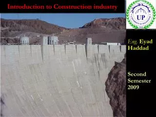
Introduction to Construction Drawings Module 00105-09. Objectives. Upon completion of this module, you will be able to: 1. Recognize and identify basic construction drawing terms, components, and symbols. 2. Relate information on construction drawings to actual locations on the print.

nicolasm
Download Presentation

Introduction to Construction Drawings Module 00105-09

An Image/Link below is provided (as is) to download presentation Download Policy: Content on the Website is provided to you AS IS for your information and personal use and may not be sold / licensed / shared on other websites without getting consent from its author. Content is provided to you AS IS for your information and personal use only. Download presentation by click this link. While downloading, if for some reason you are not able to download a presentation, the publisher may have deleted the file from their server. During download, if you can't get a presentation, the file might be deleted by the publisher.

E N D

Presentation Transcript


  1. Introduction to Construction Drawings Module 00105-09

  2. Objectives Upon completion of this module, you will be able to: 1. Recognize and identify basic construction drawing terms, components, and symbols. 2. Relate information on construction drawings to actual locations on the print. 3. Recognize different classifications of construction drawings. 4. Interpret and use drawing dimensions.

  3. Performance Tasks • 1. Using the floor plan supplied with this module: • Locate the wall common to both interview rooms. • Determine the overall width of the structure studio. • Find the distance from the outside east wall to the center of the beam in the structure studio. • Find the elevation of the slab.

  4. Figure 1 – Types of construction drawings

  5. Figure 2 – The title block of a construction drawing

  6. Figure 3 – The revision block of a construction drawing

  7. Figure 4 – Sample legend

  8. Figure 5 – Civil plan, aerial view

  9. Figure 6 – Landscape plan

  10. Figure 7 – Roof plan

  11. Figure 8 – Exterior elevations

  12. Figure 9 – Section drawing (wall section).

  13. Figure 10 – Detail drawing (ceiling detail)

  14. Figure 11 – Window schedule and window detail

  15. Figure 12 – General notes for structural plans

  16. Figure 13 – Foundation plan (foundation/slab-on-grade plan)

  17. Figure 14 – Structural section drawing (foundation details)

  18. Figure 15 – Mechanical plan general notes

  19. Figure 16 – Mechanical plan legend

  20. Figure 17 – Mechanical plan list of abbreviations

  21. Figure 18 – P&ID

  22. Figure 19 – HVAC drawing (1 of 2)

  23. Figure 19 – HVAC drawing detail (2 of 2)

  24. Figure 20 – Mechanical detail drawing for hot water riser and drain connections

  25. Figure 21 – Plumbing plan

  26. Figure 22 – Plumbing isometric drawing (sanitary riser diagram).

  27. Figure 23 – Electrical plan general notes

  28. Figure 24 – Power plan (first floor)

  29. Figure 25 – Panel schedules

  30. Figure 26 – Electrical symbols list

  31. Figure 27 – Electrical abbreviations

  32. Figure 28 – Specification (air handling units) (1 of 2)

  33. Figure 28 – Specification (air handling units) (2 of 2)

  34. Figure 29 – Sample RFI

  35. Figure 30 – Lines of construction (Alphabet of Lines)

  36. Figure 31 – Abbreviations

  37. Figure 32 – Architectural symbols

  38. Figure 33 – Civil and structural engineering symbols

  39. Figure 34 – Mechanical symbols

  40. Figure 35 – Plumbing symbols

  41. Figure 36 – Keynotes

  42. Figure 37 – Grid

  43. Figure 38 – Exterior and interior dimensions on pipe

  44. Supplemental Art

  45. Supplemental Art

  46. Supplemental Art

More Related