Download
1 / 4
40 likes | 132 Views
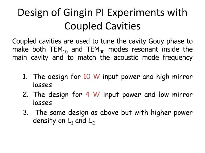
Design of Gingin PI Experiments with Coupled Cavities. Coupled cavities are used to tune the cavity Gouy phase to make both TEM 10 and TEM 00 modes resonant inside the main cavity and to match the acoustic mode frequency The design for 10 W input power and high mirror losses

E N D
Design of Gingin PI Experiments with Coupled Cavities Coupled cavities are used to tune the cavity Gouy phase to make both TEM10 and TEM00 modes resonant inside the main cavity and to match the acoustic mode frequency • The design for 10 W input power and high mirror losses • The design for 4 W input power and low mirror losses • The same design as above but with higher power density on L1 and L2
1. High loss configuration with 10W input power N E W 1440 mm 1.22 S 1008 mm M0 L1 400 mm ETM ITM L2 M2 M1 Intra-cavity 10.8 KW 72860 mm 9370 mm If Qm = 106 ,m = 2 105 Hz and Meff= 0.5 kg, the resulting parametric gain R 1. The M0, M1 and M2 are keeping fixed and the position of L1 and L2 are adjusted for mode matching. The corresponding tuning efficiency is approximately 5.5 mm/ KHz, which means to achieve1 KHz frequency difference tuning between TEM01 and TEM00, one need to displace L1 and L2 about 5.5 mm around the center position. * The relocation of L1, L2 and M0 in centimeters will compensate the manufacturing error of mirror radii of curvature.
2. Low loss configuration with 4W input power N E W 1440 mm 1.22 S 1008 mm M0 L1 400 mm ETM ITM L2 M2 M1 Intra-cavity 12.8 KW 72860 mm 9370 mm If Qm = 106 ,m = 2 105 Hz and Meff= 0.5 kg, the resulting parametric gain R 1.2 The M0, M1 and M2 are keeping fixed and the position of L1 and L2 are adjusted for mode matching. The corresponding tuning efficiency is approximately 5.5 mm/ KHz, which means to achieve1 KHz frequency difference tuning between TEM01 and TEM00, one need to displace L1 and L2 about 5.5 mm around the center position. * The relocation of L1, L2 and M0 in centimeters will compensate the manufacturing error of mirror radii of curvature.
3. Low loss configuration with 4W input power but high power density N E W 1440 mm 1.22 S 1008 mm M0 L1 400 mm ETM ITM L2 M2 M1 Intra-cavity 15 KW 72860 mm 9370 mm If Qm = 106 ,m = 2 105 Hz and Meff = 0.5 kg, the resulting parametric gain R 1.8 The M0, M1 and M2 are keeping fixed and the position of L1 and L2 are adjusted for mode matching. The corresponding tuning efficiency is approximately 6.4 mm/ KHz, which means to achieve1 KHz frequency difference tuning between TEM01 and TEM00, one need to displace L1 and L2 about 6.4 mm around the center position. * The relocation of L1, L2 and M0 in centimeters will compensate the manufacturing error of mirror radii of curvature.